Search This Blog

Sunday 9 December 2007

Stage One Build Complete..

When I started out on this venture, the different products I had looked at and ordered, collectively formed an image of what the final robot would look like. I'm really pleased to have gotten this far, and have achieved what I had originally set out to build.

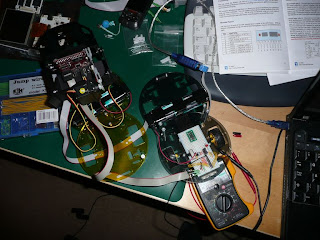
For your pleasure, below are photos of the initial Stage One prototype build.

There have been a number of changes from previous photos.
1) Four wheel drive, almost ;) - As an experiment I added a second dual axis gearbox and motors. Piggy-backing the driving of these motors from the single Pololu motor controller. I also tried this with just the gearboxes and no motors. It works suprisingly well in a straight line, but cannot turn to save it's life. With the weight of the Robot and low torque of the motors it just couldn't get enough drive to turn. Lots of stalling (on smooth and rough surfaces) meant the thermal cut-off in the motor controller to kick in.
2) VC21RB1 - I've added into the VC21 COG stack the Robot Controller (VC21RB1). And mounted the stack on another Pololu round robot chassis base. Space was getting really limited on previous versions, but I now have a mid-deck to mount anything (particularly power supplies).

This initial prototype build has taught me loads. And as predicted the tiny Pololu motor controller and Tamiya gearboxes and motors are really straining under the weight. I'm not throwing away the motors and gearboxes just yet though. I'm waiting on Virtual Cogs to release some example code for the VC21RB1 controller, and am ready to hook that up and test it out. Then in the new year it's onto the second prototype stage of changing the chassis to a track based system (probably the Robotics Connection Level 1 Traxster Robot Kit).

As far of what is working. All parts are working seperately. The CMUCam3 is connected and working with the Pololu motor controller (controlled via a laptop). The VC21 stack is working fine, but not tried connecting this up to the CMUCam3 yet. I need to get underway with VC21 COG development (particularly the I2C, UART, and LCD driver software) before going further with hooking up that final sub-system of this robot.


Wednesday 28 November 2007

Consumed..

Consumed with research paper reading (see new list to the right). Some great work out there. Just narrowing down directions to take. Really want to get some practical work done with neural nets and genetic algorithms, but can't be too hasty with those yet :)

Monday 19 November 2007

The story so far..

A requested update to show my current progress..


URL Key :-

  1. CMUCam3 with Turret Assembly,
  2. Tamiya Twin-Motor Gearbox,
  3. Pololu Micro Dual Serial Motor Controller,
  4. VC21BR1,
  5. VCMX212,
  6. VC21MM1,
  7. Pololu Round Robot Chassis

And the interfaces between the three main systems..


Last week I was hooking up OpenCV with the CMUCam3. I now have a test harness running on the laptop that can grab frames from the CMUCam3 and feed them into OpenCV routines.

Also still battling with the CMUCam3 MMC HAL driver..

Falling behind with keeping up to date with Heroes (S2), Dexter (S2), Bionic Woman, Dirty Sexy Money, ... And consumed with Call of Duty 4 (PC) at the moment..

Wednesday 14 November 2007

Distractions

A long overdue post..

I've moved across to looking into why the CMUCam3 HAL driver firmware doesn't like the PQi MMC card I'm using with it. Without access to a scope/analyser it is slow going. I'm testing a custom firmware to step through the MMC SPI startup sequence. So far no indication why it doesn't like the SPI CMD0 sent to the card. Need to head back to that code this week to delve further..

I've also started to hook up OpenCV to the CMUCam3. As a starting point I'm using David Staven's Sparse Optical Flow Demo(PDF) code and AVI. Changing it to UART-talk to the cc3 module and grab camera frames (via a modified CMUCam2 emulation firmware). The Visual Studio workspace is setup, the OpenCV demo working, just need to work on the cc3 interfacing. Then I have a testbed framework to start various image processing experiments :)

Finally, Call Of Duty 4 (PC)... This has sucked up loads of my time. Played solidly all weekend and this week. An initial eight hour stretch to complete single player, before jumping into multiplayer madness.

Wednesday 7 November 2007

CAM_RESET

I put a post on the CMUCam forum describing the problems I have with the CAM_RESET line on the CMUCam3 module. And one of the CMUCam developers kindly replied confirming my fears. That line is used to reset the OV6620 camera module, and needs to be pulled low and left along. So it can't be used as a GPIO line connected to the Pololu uDSMC reset pin :( I had thought about dropping in a transistor invertor circuit so that the CAM_RESET could be held low until a motor controller reset is required and a high pulse on that line could have reset the controller (with the appropriate HAL/OV6620 reinitialisation). But with that the mysterious half-voltage drop seen on the CAM_RESET line, it left me fearful of using that approach. Best to leave the camera alone to do it's magic.

The forum reply did make a great suggestion :) I'm only using two of the four servo outputs on the CMUCam3 (for the pan and tilt servos in the turret assembly), so have the spare two servo outputs for use as GPIO lines. I need to make some other cabling to hook it up, but great to have a proper solution for resetting the motor controller.

With that sorted I'm going to head back into the MMC code in the CMUCam3 HAL driver. Fingers crossed I can work out why the current code doesn't like the PQi MMC card I have, then onto fixing it..

Sunday 4 November 2007

Time for some interfacing..

Before I get onto the interfacing adventure, here's an annoying problem I faced yesterday with the CMUcam3..

I picked up a cheap PQi 256MB MMC card for the CMUcam. Got back home and took the turret assembly apart to fit the MMC card. Reassembled the turret and flashed the CMUcam3 with the 'hello-world' example project. No joy trying the initial file write test in that example. Added some printfs into the HAL driver and hello-world example, and reached a 'DOH!' moment. I hadn't formatted the MMC card for FAT :(
Took turret assembly apart, formatted the MMC card for FAT, reassembled the turret, and tried again.. Still no joy :( I had a dig around further in the mmc_driver and mmc_hardware functions. Referencing datasheets on the SPI programming of an SD/MMC card, it looks like the HAL driver has very limited implementation for MMC cards. The CMUCam WIKI and forum also mention that only certain cards work and some others that CMU guys have tried don't work. So something else to add to the todo list..

Onto interfacing fun..


With the double decker chassis built earlier in the week, it was time to have a closer look at the interfacing of the three systems; VC21 stack, CMUCam3, and uDSMC. Interfacing the VC21 and CMUCam3 should be easy. The VC breakout board has UART4 to connect to the UART0 on the CMUCam3. The issue then was how to get serial data to the Pololu uDSMC board, plus the issue of how/where to get a GPIO line to the reset pin of the uDSMC.

Re-reading the CMUCam3 datasheet lead me to a mini-Eureka moment. The LPC2106 has dual UART built in and CMU have sent UART1 through to a second IDC connector on the module (the Expansion port GPIO). It also looked like the CAM RESET (P0.15) GPIO could be used for the uDSMC reset line. The UART1 sent to the expansion port is already at TTL levels, so no need for the MAX232 line driver, freeing up valuable space for the DE-ACCM2G accelerometer board :)

I made a cable to connect the expansion port IDC socket to the breadboard (only need three lines from it, GND, CAM RESET, and TX2). Then onto changing the 'CMUCam2 emulator' example project to handle GPIO changes and UART1.

It took a little bit of work to get the CAM RESET GPIO setup. The below code is now used to initially select P0.15 as a GPIO output, pull it low for 100ms, before turning it high and keeping it high.
// CAM RESET(P0.15) bit selector
#define CAM_RESET 0x00008000
// Make P0.15 a GPIO
REG(PCB_PINSEL0) = REG(PCB_PINSEL0)&0xCFFFFFFF;
// Set P0.15 as output
REG(GPIO_IODIR) = REG(GPIO_IODIR) | CAM_RESET;
// P0.15 low, to reset motor controller
REG(GPIO_IOCLR) = CAM_RESET;
cc3_timer_wait_ms (100);
// Raise P0.15 high
REG(GPIO_IOSET) = CAM_RESET;

The UART1 setup was a lot easier. The cc3 HAL library is already setup to handle the second UART. It was then just a simple case of adding another input command to the example code. The following shows a simple way to send serial commands to the Pololu uDSMC.

cc3_uart_init (1, CC3_UART_RATE_9600, CC3_UART_MODE_8N1, CC3_UART_BINMODE_BINARY);
FILE * fp = cc3_uart_fopen(1,"r+");
if (fp == NULL)
{
printf("UART1 is dead\n");
while(1);
}
unsigned char buf[8];
// Both motors forward at half speed
buf[0] = 0x80; // Start byte
buf[1] = 0x00; // Device type
buf[2] = (0x00<<1) | 0x1; //M1 forward
buf[3] = 0x40;
buf[4] = 0x80; // Start byte
buf[5] = 0x00; // Device type
buf[6] = (0x01<<1) | 0x1; //M2 forward
buf[7] = 0x40;
for(int i = 0; i < 8; i++)
{
while((REG(UART1_LSR) & LSR_THR_EMPTY) == 0);
REG(UART1_THR) = buf[i];
}
fflush(fp);
I don't think the fflush is needed (and might not even be setup properly) because the cc3_uart_init already setups UART1 to flush it's FIFO after 8 bytes have been written to it. I need to have a further look to see if this is the write way to write out serial data via the UART registers, and whether the HAL code is behaving and thourough.

So two extra commands have been added to that CMUCam2 example firmware image. I've hooked up the 'FW' command to send the motor on commands to the uDSMC, and added the 'MR' command to CLR and SET the P0.15 GPIO line to reset the motor controller. These commands can be sent via the CMUCam3 Frame Grabber program.


Issues..
So far this 'almost' works. The uDSMC picks up the serial commands and starts turning the motors/wheels. BUT, and a big one, is that after X milliseconds (over 400ish) the P0.15 GPIO line drops half it's voltage and I guess resets/disables the uDSMC stopping the motors. Hmmmm...

Something to look at in the week.

That's all for now folks..

Wednesday 31 October 2007

Super cute

On arriving home tonight I had the Technobots order waiting for me :) Dinner was put on hold for a few hours while I started to assemble the second deck of the robot.

Included in the order is the tiny Dimension Engineering 2D accelerometer board. It will have to wait until the weekend to test it out, and also rearrange the existing breadboard (housing the Pololu uDSMC and MAX232 circuitry).


I couldn't wait to blog-share photos of the upper deck constructed, including the mounted CMUCam3 turret assembly :) How cute is this...


Saturday 27 October 2007

This weeks roundup..

Another week of chipping away at stuff. My main attention has been with the CMUCam3 module. I've been able to flash various example firmwares to the CMUCam3 and it's all working lovely.

I now have two GNU Arm tool chains on the laptop. The Yagarto GNU ARM toolchain for MX21 (ARM9) work, and the CodeSourcery "G++ for ARM EABI" one for CMUCam3 (ARM7) work. As far as setup goes; the CodeSourcery toolchain takes priority (directory PATHs, etc.), with the Yagarto one being enabled via the custom makefile scripts used for MX21 work.

I've also place an order with Technobots (UK) They were a later supplier find, stocking quite a few parts I had ordered from the US, including the Pololu parts. My original Pololu order had four round robot chassis bases, but I forgot the spacer rods on that order. So I was able to grab two sets of spacers from Technobots. The intention currently is to put the four round bases together to form two platforms. Drill through the front top one to make a place to securely mount the turret assembly, and have the top back one somewhere to put the VC21 stack. Hopefully with enough space on the bottom deck to place the motor controller board and power supplies. Then it's back to determining whether the tiny motors and gearboxes can handle that much weight. My current gut-feeling is that they can't..

Technobots have also start supplying Dimension Engineering's Accelerometer boards. So I've order from them the +-2g Buffered 2 Axis Accelerometer module DE-ACCM2G. I've been using a similar MEMS device in the Nintendo Wii development in my day job, so I'm familiar with the intricacies of analysing the noisy output from a MEMS chip (to check out the internals of a Wiimote, head over to this SparkFun tutorial). The 5g Accelerometer module from Dimension Engineering uses the same Analog Devices chip used in the Wiimote. I'm hoping the smaller 2g device is just as sensitive, if not more so.
I can't wait to get this tiny module and hook it up to the ADC on the VC21RB1. The VC Robot COG has a LPC2136 (ARM7TDMI-S) core that contains two 8-channel 10-bit ADCs. Perfect for connecting the X-Y outputs of the DE-ACCM2G accelerometer. With this hooked up on the robot it will then be able to work out it's orientation vector with respect to gravity. I'm also think about using it in conjunction with the CMUCam3 analysis to determine if the motor controller has gone crazy and needs to be reset.

Another bit of software to add to this mix is RoboRealm. I picked up a while back a very cheap USB web camera. So cheap it's default resolution is CIF (352x288), intentionally the same as the OmniVision CMOS camera sensor module used on the CMUCam3. I should be able to prototype an image processing pipeline for the CMUCam3 using RoboRealm, before moving this across to CMUCam3 firmware. Initial results from experiments in RoboRealm look encouraging, but I know it's going to be a huge effort to move any image processing pipeline routines from RoboRealm across to the very limited CMUCam3.

Finally here's a cute photo of the CMUCam3 in it's turret assembly -

Saturday 20 October 2007

MAX232, uDSMC, CMUCam3

It's been a busy week in and out of work, so only been able to chip away at stuff.

I managed to get Irrlicht compiled and linked into a VC21 example (touch example). Plus using the Insight/GDB/OpenOCD/JTAG combo to download it to the MX21 board. It took some makefile monkey'ng to get it built though. Rolling in at a wooping 18MB elf it took quite a while to download. I only enabled a stub device and display drive, but managed to step through to the Irrlicht startup code. Although Irrlicht is quite bloated with some lovely features I intend to use in the future, it's a bit too much for this initial setup work. So for the time being that side of this project is on hold.

The Pololu chassis and motor controller testing I blogged about earlier. The initial setup of the uDSMC used the simple RS232 converter circuit described in the uDSMC manual to check all was working fine. In the week I popped into a local electrical shop and picked up a MAX232 IC and 7805 DC/DC regulator. These are now used as the main RS232 converter for the Pololu uDSMC and chassis.

A variety of schematics were used as reference to setup this circuitry, for example;
http://www.digitalnemesis.com/info/projects/picservo/article.aspx
http://www.flickr.com/photos/todbot/94701997/in/set-72057594051313379/
http://www.iguanalabs.com/adc2051.htm

The motors are powered straight from the battery source, and the MAX232 and uDSMC are powered from the 7805 regulator. This all works very nicely, and seems more stable. So far no heat problems.

It's now possible to revist the power input for this chassis. I ran out of breadboard space to add a power LED and power switch, so need to look into that at a later date. I'm also only using half of one of the dual RS232 line drivers inside the MAX232 (to pull down the RS232 signals to TTL levels needed for the uDSMC), but it does allow for future expansion. It's now possible to add quite a variety of other TTL based devices to this circuit (e.g. sensors, alternative motor drivers). Eventually I'll transfer this to a stripboard and clean up the cabling and power connections.

Once complete I revisited the custom communication software I wrote to talk to the uDSMC. Adding to it a different way of handling cursor keys from the laptop, and using linear ramping for the speed sent to the uDSMC. Still need to revist the braking side of that code, but it was happily moving around the desk controlled from the laptop.


While setting up different software test harnesses, I had intended to start using Eclipse as my main IDE. Annoyingly though Eclipse does some daft things. It's quite an alien IDE to me, so I've ended up ditching it in favour of Visual Studios Express Edition (again free). Creating an extensive makefile system, with proper dependency checking etc. I can now use this as a template build system for further SW development. Insight and OpenOCD are also included in this setup.

Inow have a Subversion server running on the laptop. After many years using RCS it is now ingrained in my SW development pipelines. We currently use SVN at the company I'm working for. It's fairly nice, has it's quirks of course, but it's a lot better than VSS. Thinking about it though I could have grabbed Perforce to handle the SCM/RCS, but then SVN and it's shell integration works well enough.
This setup actually turned out to be really simple. Head on over to http://svn1clicksetup.tigris.org/ for a single installer based method for setting up SVN and your first repository :)


At the end of week the CMUCam3 module arrived from Seattle Robotics :)

Need to pop to the shops today to pickup a power connector for this, then I can check it out and have a play. Can't wait... :)

Sunday 14 October 2007

Source level debugging working

After the success earlier today getting GDB to work through OpenOCD via Olimex ARM-USB-TINY JTAG connector, I thought I'd revisit Eclipse and check out the Insight debugger supplied with the Yagarto tool chain.

I closely followed Jim Lynch's Eclipse/Insight tutorial (PDF link) to get Eclipse setup with CDT, Insight, and OpenOCD. His tutorial is geared towards using an Olimex prototype board, but can be easily refactored to work with Yagarto and OpenOCD.

I setup the Virtual COGs 'touch' example within Eclipse, and also setup two external tools; namely OpenOCD (using the VC config script from the VC wiki, see previous blog post) and the Insight debugger (found in the Yagarto tool chain).

With the MX212+MM1 device connected via USB (as before) and the ARM-USB-TINY JTAG connected, it was a simple case of running OpenOCD server from inside Eclipse, then calling Insight from inside Eclipse. Insight was able to run to 'main', and then source step through the code :)

After some initial teething issues, everything now seems to be falling in to place. Very encouraging. Irrilicht here I come... :)

JTAG/GDB

Before popping out for lunch I thought I'd try JTAG/GDB debugging on the MX212. Wow, how easy :) After the shenanigans of getting the right PID setup on the Olimex ARM-USB-TINY JTAG connector XP driver, I wasn't hopefull that the OpenOCD server would be properly working. I came across the config file from VC wiki for the server and sparked it up (link to config file here). OpenOCD server looked like it was running fine in the cmd window (with the ARM-USB-TINY connected first to a USB port of course).

Making sure that JP300 and JP500 (for stack power via USB) were shorted I connected up the MX212 to another USB port on the laptop. The three LEDs on the back of the MX212 were all lit, so ready to go. Also have the VC21MM1 connected to the MX212 in my current default configuration.

Using the 'touch' VC21 example, that I know worked via uMon download, I called up the arm-elf-gdb from Cygwin. Hey-presto GDB kicks into life (thanks to the .gdbinit supplied with this example) and the VC21MM1 becomes active and the 'touch' example is running. Broke into the program in GDB and single stepped the code. All working lovely.

Now just need to go back and setup Eclipse properly for JTAG/GDB work with the MX212... And then on to looking at writing that software driver for the VC21MM1 touchscreen LCD in Irrilicht.

Pololu chassis up and running...


Yesterday I had great fun setting up the Pololu chassis and controlling it via serial communication from the laptop :) After trying out my soldering on a test kit from Maplin (two LED flashing unit), I started work on the chassis and breadboard work for this ickle robot.

As recommended I soldered a 0.1uF Cermamic capacitors across the two motors and feed each pair of wires from the motors through the chassis to the breadboard. The USB-RS232 connector fed the four serial lines required through to the breadboard, with a simple transistor (2N2222A, high frequency, low power) and resistor arrangement to bring the RS232 levels down to the levels required by the Pololu micro dual serial motor controller. This could then be sent a serial bit stream that the controller would interpret and drive the internal H-Bridge to control the two chassis motors.

I had some teething trouble at first by making the mistake of driving the motor controller logic levels at too high a voltage. Ending up with a smoking motor controller :S Thankfully I had bought two of them just in case this happened.

To send the control data to the motor controller ended up being very simple. A Win32 console app, built through the free Visual Studio 2005 Express Edition IDE, opened up and setup the appropriate COM port that the USB-RS232 converter had mapped itself too (under WinXP). Configured to 9600bps, no parity, 1 stop bit, DTR/RTS turned off, and FILE_FLAG_WRITE_THROUGH|FILE_FLAG_NO_BUFFERING used in the CreateFile call to make sure device writes were not cached (although I also used FlushFileBuffers after each WriteFile just in case). It was then a simple matter of using WriteFile to send the 4 bytes worth of data to the motor controller to control the motor states. Some additional GetAsyncKeyState monkeyness allowed for forward/back/left/right movement control.

Apart from frying the original controller, and making sure that stalls didn't kick in the motor controller thermal cutoff protection, everything went very smoothly. Although this is just novice entry level experiments to get a chassis built and moving, it's a nice starting point. I can now do some stress testing of the chassis and controller, see how they fair with carrying heavier loads, and work out what improvements/replacements need to be made for the final chassis and motor control. But before that, I'm going to switch back to the JTAG debugging investigation/learning with the COGs, and setting up a decent makefile workspace (either in Eclipse or VS EE, not sure yet).

Thursday 11 October 2007

Olimex ARM-USB-TINY

I tried to get the Olimex ARM-USB-TINY working tonight with OpenOCD. At first I tried the drivers supplied with OpenOCD. No joy. Driver installation kept failing to recognize the ARM-USB-TINY device using the OpenOCD supplied driver. Thankfully it didn't take long to find out that the PID in the inf/ini driver files are for another Olimex devier and not setup for the Tiny USB version. This link http://forum.sparkfun.com/viewtopic.php?t=7629, and other posts on Sparkfun's forum, describe the changes required to the inf and ini files. After making the changes I can now get the ARM-USB-TINY device recognized and OpenOCD server running. How stable it'll be I'll check this weekend.

After seeing Rush in concert last night, and last week's holiday, time for an early night. More fun this weekend with the COGs and Eclipse...

Monday 8 October 2007

Back from hols...

Just got back from a wonderful week in Cairo and Luxor. Seen loads of sights and had a very relaxing time. Got tomorrow off to recover from the journey back and to FaceBook the photos :)

Then back to playing with the COGs and the Pololu chassis..

Saturday 29 September 2007

Getting there...

So the i.MX21 is working fine. Next up is the Multimedia COG...

First thing I tried was the 'touch' example. I used uMon, via Hyperterm, to download the elf and set it up to be executable from the flash memory. Ran it and hay-presto the touchscreen sprang into life :)

Next up I thought I'd try the 'lcd' example. Trouble is I can't get the entire elf transfered via xmodem. The Hyperterm file transfer dialog looks like it sends all of the elf, but the 'tfs ls' only showed ~4kB transfered. Of course trying to run the truncated elf throws up a simple error :(

After removing the lcd file from the flash ('tfs rm lcd') the same thing is happening with the xmodem transfer. I even tried deleting the elf and cleaning the flash 'tfs clean'. Still no joy. Even 'tfs check' says that the files in the flash are OK. Which is strange in that the 4k lcd elf should have at least check sum failed??

So next... I downloaded the HAB Toolkit from the Freescale web site (the i.MX21 variant linked from the wiki, albeit a page hidden in the wiki history). Annoyingly this only allows for setting COM 1-4. The laptop has the Silabs USB to UART mapped to COM5!!! :S And the Device Manager says that COM1-4 are in use.

Gonna take a break and see if the sub-conscious kicks in and throws up something else to try.

UPDATE:
As this blog entry comments show, Tarun from VC made a valuable suggestion. I need to have a look further, and see if this could become a common problem or not, but the lcd elf contents was terminating the xmodem transfer :( Adding some additional code to alter the final elf sorted out the transfer problems, and I am able to upload images to the LCD :) Thank you Tarun.

I can't get VC's Booter to work. It's possible that that is suffering from the flow control problem I faced when first getting started?? I'll get in touch with the author and see if problems I face with it can be sorted, and help advance the tool. Although probably after the trip to Egypt next week.

It's Alive!!!

Took a while to get Hyperterm setup, but really pleased that the i.MX21 is working :)

VC have a mistake in their VCMX212.1.pdf document. They say that the baud rate (bps) to use in Hyperterm is 460800:8N1 but this is wrong. The Wiki is correct with the 230400:8N1 They also don't mention turning off flow control. When the baud rate is set right you can see the device starting up, feeding back the uMon start up text, but then with 'Hardware' flow control set (default setting in Hyperterm) you cannot seem to send ASCII characters back to the device.

uMon is working fine, Linux starts up, ready to rock'n'roll :)

Virtual COGs package arrived

What a glorious day. Lewis Hamilton has taken pole position for the Japanese GP. There's rugby on the TV all afternoon. The sun has managed to break up the rain clouds. My belly is full of a big breakfast from the local cafe. And best of all; The Virtual COGs order has turned up this morning :)

Just going to start a magnified examination. They were very well packaged. Initial look seems to show no surface mount components that have fallen off in transit from Canada. If they all look good, I'll spark up the laptop and start playing with them (via USB and JTAG).

In this first picture;
Top row - VC21RB1 Robot COG, VC21BR1 Breakout COG, VCMX212 i.MX21 COG
Bottom row - VCLCD43 LCD with touch screen overlay, VC21MM1 Multimedia COG


Friday 28 September 2007

CMUcam turret assembly

I've had the CMUcam turret assembly sitting in a box for the last week (ordered from http://www.robot-electronics.co.uk/) waiting for certain missing tools to turn up. They turned up on Wednesday, but a party last night delayed the initial assembly. I'm also waiting on the CMUcam3 module turning up from Seattle. In the mean time I thought I'd get it built and see what size it built to. The size certainly shows that the Pololu chassis is going to be too small.

Wednesday 26 September 2007

Random babble

While waiting for the other orders to turn up (been a few more, CMUcam3 module to go with the turret assembly, big order of components/parts/tools, Pololu motor controller) I thought I'd jot down some plans and ideas.

The laptop is now charged with all sorts of dev software. Off the top of my head;
I did download Fedora 7, but had silly problems trying to get it installed on a new partition. So for the time being it's going to be WinXP and Cygwin on the laptop. Which is fine, it's what I'm used to with the Wii and other console/handheld development work over the last few years.

The Olimex JTAG and Pololu chassis are sitting lonely, hopefully the other parts will trickle in over the next week or two. Mind you with the Egypt holiday next week, it's going to be maybe a welcome break to step back and hone the direction a bit.

As for direction :p

Current plan is to get the VC21 modules working together, with precidence on the LCD touch screen working alongside the MX212. With a port of the Irrilicht engine to Linux on the MX212 So firstly looking at how that can be done. Possible need to look at a device driver for the LCD handling, and definetely a custom Irrilicht renderer.

Next up will be setting up the Pololu motor controller. Initially breadboard the device to the chassis, and feed it through to the laptop to get it tested. Naturally with the appropriate HW to make sure I dont fry it with the RS232 levels. Need more thought on this. Being a SW guy an all. Although that's the main reason to get this cheapo laptop, just incase I do muck up :) I won't!!

Then it's the CMUcam3 with turret assembly. Not checked this out further, but should be easier to test with RS232. The cam module has better handling for that than the Pololu part.

And while all that is going on, do further investigation of single and dual camera vision research.

Oh, and a trip to a hardware/DIY outlet to see what materials they have to make a bigger base. Possible to buy something like a tank-track based chassis, but want to check out whether something can be constructed around the two Pololu chassis first. But then that's getting a bit to ahead of myself. First need to determine how sensitive and accurate their movement is first, before constructing a larger platform (think 2x CMUcam3 plus turrets and VC21 stack) for this robot :)

I'll have a good think sitting by the pool next week. But currently in my mind is a vision for this little robot to move around unteathered with the CMUcam3 (eventually x2) having it's live feed pulled back into the MX212, and into the Irrlicht engine for display. Appropriate processing on the feed (with possible inclusion of ultrasonic scanning help) building up a 3D representation of the world, feeding navigation/AI. All output on the LCD :)

Then it's on to Neural Nets and Genetic Programming...

Monday 24 September 2007

First arrival

The first parts have turned up :)

Pololu have delivered the two Round Robot Chassis. And now I see how tiny they are :S Only took an hour of fun to assemble one of them. I'll keep the other for a spare, or for other robot/sensor experiments.


Sunday 23 September 2007

Shopping list (part 1)

I recently came across a, relatively, new Canadian company called Virtual Cogs (http://www.virtualcogs.com/). Their VC21 series of stackable devices is superb. I'd used ARM processors before in handheld game programming, and always like their chips. So seeing them used on a VC21 stack modules got me thinking about making a robot again.

VC's Robot COG looked perfect as the main HW interface, with the i.MX212 handling the bulk of any SW processing. Throw in the Multimedia COG with touch screen, Linux running on the i.MX212, integrated JTAG, and lots of new avenues open.

So first on the shopping list is;
  • i.MX212 COG (VCMX212) (Actually went for the Starter Kit)
  • Breakout COG (VC21BR1)
  • Multimedia COG (VC21MM1)
  • Robot COG (VC21RB1)
  • JTAG interface (VC21JTAG)
  • Assorted connector cables and mounting hardware
The next step was Pololu's robot kits (http://www.pololu.com/). Particularly the Round Robot Chassis. Impetuously I went ahead and ordered the chassis kit, with Tamiya gearbox and assorted plates. Only later reading up on the H-Bridge used in the VC21RB1 :S More on that later.
Plus it was also later that I discovered that I could have bought them from Technobots Ltd here in the UK (http://www.technobots.co.uk/). Oh well, another supplier found...

Next up was the JTAG interface. For which I went for the Olimex (http://www.olimex.com/dev/index.html) ARM-USB-TINY and ARM-JTAG (as backup, just in case OpenOCD had trouble with the USB varient). Ordered these via Sparkfun Electronics (http://www.sparkfun.com/).

Another great find is the CMUCAM2 and, importantly, the pan/tilt turret head and servos. This time I got it from Active-Robot :) (http://www.active-robots.com/products/accessories/cmucam.shtml). Only one of these to start with, but I'll grab another further down the line.

Finally, in this first line of purchases, is a cheap laptop from eBay. Took a couple of days to win a good bid, but managed to get an IBM Thinkpad T42 for under £200.

Yay, first purchasing round is complete. Now just need to wait for it all to turn up.

In the mean time I can start at getting together all the development software required...

Friday 21 September 2007

Introduction

As the colder autumn months draw closer, I thought it might be time to start a new hobby.

My first job after Uni was working on custom graphics cards (used in commercial and military simulators). This was back in the early '90s, but was a great introduction to low-level software development alongside some great hardware and software engineers. Since then I've been fascinated by hardware and software and built a career around it. Although for the last 10+ years I've been working in the computer/console games industry.

Every now and again I've looked around for off the shelf HW parts to piece together and make some form of robot that could also 'see'. The last few weeks have been fantastic, finding all sorts of evolved HW and SW.

It's finally time to start :)