Search This Blog

Saturday 16 October 2010

Re-programming the ROB-09571 (Serial Controlled Motor Driver)

Sparkfun's Serial Controlled Motor Driver is a lovely board. It has been working great in Project: Burt. One thing I've been meaning to do though is to change the firmware it is supplied with. Various comments suggests that this is possible with an Arduino, so I spent the morning having a look into this.

The first thing is to get the firmware re-compiled. For that we need to download and unzip the firmware supplied by Sparkfun. Inside the zip file are three files; main.c, main.h, and a Makefile. The Makefile points to using WinAVR to rebuild this code. A quick trip via the WinAVR website, takes us to the download location on SourceForge. I used the latest installer file called WinAVR-20100110-install.exe Choosing the default install options, and making sure that the PATH environment variable was updated.

Opening up a cmd prompt and navigating to the unzipped firmware, it was then a simple case of using 'make clean' to verify that WinAVR was installed ok. Then 'make all' to rebuild the firmware. From the resulting files we only need the main.hex and main.eep files. These contain the hex dump ready for uploading to flash memory, and the EPROM (eep) file ready to burn into the ROB-09571.

So far so good. The next step was working out how to turn an Arduino into an AVR ISP programmer.

Looking at the Deumilanove and the ROB-09571, they both have ICSP headers breaking out the SPI lines.


On the Duemilanove the 6-pin header is clearly labelled. On the ROB-09571 you need to solder on a header (in my case, design of Project: Burt restricted me to a two row right angle header). On both boards pin 1 is conveniently labelled (top left of each header). A quick look at the Deumilanove schematic and ROB-09571 schematic shows that all the neccesary ICSP lines are connected to the 328p ICs. So it should be a simple case of connected pin 1 to pin 1, pin 2 to pin 2, etc. That sounds far too easy, and it is :)

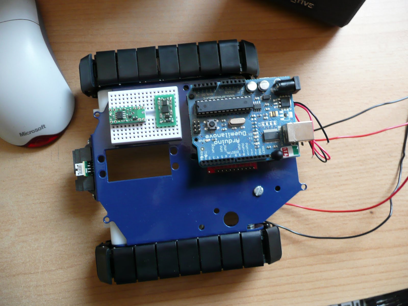
Next is what code do we need to upload to the Arduino. I'm currently using version 018 of the Arduino SDK Included is a sketch called ArduinoISP. Looking at this code, it recommends adding three LEDs (and current limiting resistors) to three of the Arduino digital pins. A tutorial describing how to connect the LEDs to an Arduino can be found over at LadyAda. Below is my initial wiring setup.

BEWARE: This wiring setup will never work! Read on for why it doesn't work.


All three LEDs use 470 ohm resistors to limit current, connected with a common ground (blue wire). The green LED is connected to D9 (green wire), the red LED connects to D8 (red wire), and the yellow LED connects to D7 (white wire). These LEDs are used by the ArduinoISP sketch to inform you of progress and/or errors. The six green wires connect the two ICSP headers.

Uploading the ArduinoISP sketch to the Duemilanove we are now ready to try reflashing the ROB-09571. But WAIT!! One vital wire is in the wrong place!!

Looking at the Duemilanove schematic it clearly shows that pin 5 of the ICSP header is connected to the 328p RESET pin! This is fine to reset all boards connected via ICSP, but the ArduinoISP sketch requires a seperate slave reset. A quick fix is to disconnect the green wire to pin 5 of the ICSP header, and connect D10 from the Arduino to pin 5 ICSP header on the ROB-09571. This now agrees with the expected wiring connections in the ArduinoISP sketch. An alternative is not to use the ICSP header, and connect to D10, D11, D12, and D13 on the Arduino.

At last. A correct wiring setup! Now it's time to flash that hex file.


We now need to use a program supplied with WinAVR called AVRDude. This communicates with the ArduinoISP sketch, and uploads the hex file to the ROB-09571.

The first thing we need to do is test that the Arduino, plus ArduinoISP sketch, and the wiring is working ok. Use the following cmd prompt line (changing com21 to the port you have your Arduino connected);
avrdude -p m328p -P com21 -b 19200 -c avrisp -v
You should eventually see;
avrdude: AVR device initialized and ready to accept instructions
If you receive any form of errors (protocol, sync, etc.), check your wiring.

We are now ready to upload our new ROB-09571 firmware. We can simply use the following commands;
avrdude -p m328p -P com21 -b 19200 -c avrisp -v -U flash:w:main.hex
avrdude -p m328p -P com21 -b 19200 -c avrisp -v -U eeprom:w:main.eep
AVRDude prints out some nice progress text. And the yellow LED should flash rapidly when the programming occurs.

When AVRDude has finished succesfully, you then have completed uploading new firmware to the ROB-09571 :)

Sunday 27 June 2010

Project: Burt - Assembly #3 Motor Interfacing (Part 2/2)

Now that we have the motor controller breakout board, and chassis insulation, we can fix in the Serial Motor Controller board.

A small plastic 'pop' rivet came as a spare with the chassis kit. With the millimeters of thickness added by the insulation layers, it snuggly hugs the controller board when fastened in place.


Next we can add the Deumilanove board and route the IR sensor wires into the ScrewShield.


Now for the rest of the Arduino stack. The three yellow wires (male to female leads) connect the Motor Controller TX, RX, and Gnd to the Arduino D2, D3, and Gnd. A WIP PDE file (Note 1) has been uploaded. The video below shows this simple test code running. The code uses the NewSoftSerial library from Mikal Hart. This allows us to use the appropriate baud rate (115200) to communicate with the motor controller.


Everything squeezes in nicely.


Here is Burt moving around. The uploaded PDE code rotates the tracks and moves forward and backward. It clatters and drifts about on the smooth floor.


The current (original) firmware in the motor controller only accepts 9 different speeds per motor. So I need to change the code to ramp up to a certain speed (or reprogram the motor controller firmware, ideally).

I've also removed the Pololu power switch from the breadboard, with it in place and hooked up it does provide smoother power on switching. So I'll likely add it back in, or swap it out to try passive filtering of the IR sensor signal. Alternatively I could hook in the spare button on the ProtoShield. Add code into the setup() function that waits for the button press before dropping into the main loop() function.

Even with the accelerometer detecting the motion of the chassis, my current thoughts (in relation to the motion and drift) is to upgrade the accelerometer breakout board with a 6DOF IMU (including compass/gyroscope).

Smoothing the motion and clatter needs some thoughts. The CMUCam3 shifts the centre of gravity quite high, helping to exagerate the movement of the camera and servo frame. Without smooth motion, object tracking with the CMUCam3 is likely to be bothersome..

Notes:
1 - SVN revision r41 (at the time of writing)

Saturday 26 June 2010

Project: Burt - Assembly #3 Motor Interfacing (Part 1/2)

It's time to look deeper into adding the Serial Motor Controller. A couple of custom items need fabricating.

From Project: Burt

The first job was to add some insulation between the motor controller board and the chassis.
A local RC Models Shop had some thin perspex sheets that are ideal for snipping and drilling.
With a simple paper template used to get the area right. Four holes were made to help it align over the battery containers screws and rivet. Taped down that sucker is not moving.


The second item is a small strip board to connect the motor wires, motor power, and Arduino digital IO pins (for TX, RX, and Gnd). I've added one of the blocks from the ScrewShield to take in the 9V battery wires. The four motor wires connect to this strip board. The 9V lines feed into Gnd, and into Vcc via a switch plus LED (and resistor). Jumper wires routed underneath the switch make this the Off position. When toggled, it will be easy to trip this kill switch, and drain the power to the motor controller.


I've added a ScrewShield to help with other interfacing. The three wires from the IR sensor (Vo, Gnd, Vcc) are hooked up (A2, Gnd, 5V).


Plus the addition of the CMUCam3 :)

Tomorrow I'll be posting the second part, along with a video of Burt coming to life :D

Project: Burt - Assembly #2 Sensors

Onto my second video showing the next assembly step.
(Head to 1:25 in the video to skip to the breadboard layout)


I've assembled and added a ProtoShield, partially using atomicsalad's guide here. NOTE: The usual way to assemble this shield, is to have the female to male connectors aligned with the others in the Arduino stack. I have changed this so that they line up next to the breakboard, and used male headers to connect to the Duemilanove. The height of this shield, with a breadboard and breakout boards, ensures that this will be at the top of the Arduino stack. Which won't be a problem, getting too high will shift the centre of balance.

The breakboard nicely fits the Pololu Power Switch LV and Digital Dimensions accelerometer breakout boards.

The power switch was bought out of impulse. I only noticed during assembly that it is the LV version, Doh! It's too soon to work out the power consumption for the Arduino and sensors. So right now it's just there for testing. If the digital side of Burt can handle the 4x AAA 1.5V batteries, then I could use the switch (to power on the stack, and digitally power off the stack).

After years of practice and a lot of patience, my Google'ing turned up a fantastic practical discussion of accelerometers by Starlino.com - "Accelerometers reviewed and tested. Part 1: DE-ACCM2G (ADXL322), LIS244AL, Pololu MMA7260QT".

I bought the DE-ACCM2G board a few years back. Digital Dimensions have updated that product to a newer MEMS part since then. But thankfully for me I have the ADXL322 chip on my DE-ACCM2G board which fits in with Starlino's testing.

For those that wish to dig further into the depths of MEMS response and filter issues, Starlino has a follow up post entitled "Accelerometer benchmarks. Part 2: LIS331AL and DE-ACCM2G (ADXL322). Filters, amplifiers and vibration response".

I've uploaded Work-In-Progress (WIP) PDE code that grabs data back from the ADXL322. (See Note 1 below for SVN version numbering)

Seeing how stable the data is, backed up with Starlino's analysis, was wonderful to see. After working on a few Nintendo Wii game contracts, I was familiar with analysing the ADXL322 feedback from the WiiMote. But comparing what I remember about the WiiMote data and the buffered data it certainly is poles apart. So much cleaner. It also will save valuable cycle time not having to implement software filtering for this signal line, Result! I can now just play with thresholding the values to deduce what the chassis thinks it's doing, in relation to what the motor controller thinks :)

Next up is the testing of the IR sensor. The Sharp IR sensor is hooked up to Analog pin 2 (Vo), Ground (Gnd), and 5V (Vcc) lines. More WIP PDE code (Note2) (and more here) (Note3) has been uploaded that tests the analog reading and converts it to an approximated distance value. The distance conversion function is described in this Oomlout.com PDF guide. Initial testing shows the sensor sending back sensible values. Further testing is required with the IR sensor data. I'm curious to see how software filtering compares to passive filtering. Theirs certainly spare breadboard lines that could be used for it.

Right, time to look at hooking up the motor controller...

Notes:
1 - SVN version r35 (at the time of writing)
2 - SVN version r38
3 - SVN version r40

Sunday 13 June 2010

Project: Burt - Assembly #1 Chassis

Here's a short video showing the initial chassis assembly.


As mentioned in a previous blog entry, I have assembled the RobotShop Robot Rover for Arduino tank kit. I followed the excellent assembly video here.

On the front there is a Sharp IR sensor (GP2Y0A21YK). It's three wires (Vo, Gnd, Vcc) are fed underneath the chassis and emerge through a hole. These three wires have also had male jumper leads spliced onto them, to make it easier to test via a breadboard. The 9V battery wires, and four motor wires are also routed through the chassis.

From my first robot I have some standoffs that fit nicely to the servo mounting points on the chassis (Pololu standoffs). I also have the CMUCam3 assembled and ready for use, once the main robot is up and running. Note: that this won't be the final camera module. The CMUCam3 is just ready for me to use now. I need to get two cameras huddled on the front of Burt for stereo vision libraries.

Underneath the chassis the four 1.5V batteries and 9V battery are ideally placed to connect to the motor controller and micro controller.

On the left of the video is a hint as to the next update. The testing of the ProtoShield, IR sensor, PowerSwitch, and Accelerometer.

Sunday 6 June 2010

[Burt] What are the chances?

I was flabber-gasted to discover that no one in the world has ever thought of creating a Google Code project called 'burt'!! I must omit that the project name came before checking with Google Code to see if it could exist as a project name :D

I've just finished the initial Google Code Project setup. The main index is here, and also in this blogs 'Handy Links' section on the right of this page.

Why 'Burt'? I may hear you cry. Simples really. "The Dukes of Hazzard" remake was on the TV at the time when I was trying to decide on the name, and Burt Reynolds steals every scene he's in.

Project: Burt

Introduction

After a couple of years of life changes, the itch to revisit robotics has taken hold. The first robot was something that I rushed into and made some crutial, and costly, design mistakes. This time around I have had time to revisit new products and come up with a new robot design, 'Project: Burt'.

It's been great re-visiting web sites and forums I have been to before, such as Sparkfun and Pololu. It was also encouraging to find two UK suppliers that I hadn't seen before, namely Cool Components and SK Pang.

Being away from the home-brew robotics community, for almost a year and a half, has meant that I had some catching up to do with the evolution of robotics parts. Immediately three parts jumped out at me; Robot Rover for Arduino (Tank Kit), Serial Controlled Motor Driver (ROB-09571, ATMega328), and the Arduino Duemilanove (ATMega328).

The ATMega328 used in the Duemilanove and Serial Controlled Motor Driver (SCMD), looks like a perfect micro-controller to use as a sensor analyser and communications hub. Plenty of digital IO and analog inputs to play with. It was a bit overwelming, and warming, to see the rise of the Arduino products. A heathy development community has sprung up. As I thought about various sensors, controllers, communication sub-systems, most of my questions as to what to use, and how to use/connect them, were answered via Arduino's wonderfull web portal and forums.

Design List

Within a few weeks my thoughts for 'Project: Burt' were starting to come together. As a starting list I had the following in mind;

Arduino Duemilanove
- As the main controller.

Robot Rover for Arduino
- As the main chassis.

Serial Controlled Motor Driver
- As the motor controller (incl. overcurrent detection).

Pololu Pushbutton Power Switch LV
- As a potential power switch for the motor controller.

Dimension Engineering Accelerometer (DE-ACCM2G)
- A buffered ±2g accelerometer based on the Analog Devices ADXL332.

IR Range Sensor (Sharp GP2Y0A21YK)
- Included with the Robot Rover kit.

Ordering

Two orders later, I have a desk full of parts :)


Included in the orders we're a handfull of other goodies; An Arduino Starter kit (C), an Arduino ProtoShield Kit, and a couple of MCP23008 and MCP23016 IO extenders (with I2C interface) for future expansion (e.g. LED segments, Servos, USB host connection, VirtualCogs interfacing, etc.).

Physical Layout


The Arduino is placed on two stand-offs, so there is about a 1cm space below it to mount the motor controller. If any heat issues arise there are other mounting holes on the chassis to use. But for the moment this looks like a good starting point.

The main boards that need individual testing;


And so, it begins

Over the next few weeks (months) I'll be continuing along like my first robot blogging. Fleshing out the Google code project with links, Arduino PDE code, Eagle schematics, more photos and videos. A detailed step-by-step guide to getting Burt up and running.

Unlike the muddled mess that was my first robot, Burt is so far shaping up to be a nice project to get back into robotics. Plus a new starting point for vision experiments. Maybe I'll be able to get the old Virtual COGs boards dusted off and make use of the lovely Freescale i.MX21 266MHz ARM9 processor, and maybe save up for something like the Surveyor Stereo Vision System...