Search This Blog

Wednesday, 16 December 2015

Parallella Board Notes (WIP)

SDHC cards tested;
Samsung 32GB Evo MicroSDHC (UHS-I Grade 1 Class 10)
SanDisk 16GB MicroSDHC (Class 4)

After burning headless image to SDHC card, use Putty to connect via SSH to the board.

Login to board - Username: Parallella Password: Parallella

Check SD card space with: df -h

Find root partition with: dmesg | grep "root"

Run fdisk to rebuilt the root partition: See https://parallella.org/forums/viewtopic.php?f=49&t=1373

Shutdown the board with: sudo shutdown -r now

Power off the board.

Power on the board and SSH login again with Putty.

Resize root partition with: sudo resize2fs /dev/mmcblk0p2

Check new SD card space with: df -h

Update system software with:
sudo apt-get update
sudo apt-get upgrade

Reboot the board: sudo reboot

Putty will lose connection. Restart putty and login (it may take time to reboot).

Update super-user password (make it something that's remembered, e.g. linaro)
sudo su
passwd
exit

Setup Git with user.name and user.email
https://help.github.com/articles/set-up-git/

git config --global push.default simple

Install cmake: sudo apt-get install cmake
Optional cmake-gui: sudo apt-get install cmake-qt-gui

Update cmake to latest:
wget https://cmake.org/files/v3.4/cmake-3.4.1.tar.gz
tar xvf cmake-3.4.1.tar.gz
cd cmake-3.4.1
cmake .
make
sudo make install
Add export CMAKE_ROOT=/usr/local/share/cmake-3.4/ to .bashrc (then shutdown and relogin)
Check cmake is version 3.4: cmake --version

Install eog for image viewing: sudo apt-get install eog


http://www.browndeertechnology.com/docs/app_note_epiphany_parallella_build.pdf

wget http://www.mr511.de/software/libelf-0.8.13.tar.gz
wget http://github.com/downloads/libevent/libevent/libevent-2.0.18-stable.tar.gz
wget http://www.hyperrealm.com/libconfig/libconfig-1.4.8.tar.gz

Extract all and usual; ./configure ; sudo make install
flex --version
bison --version
m4 --version

echo $PATH
echo $LD_LIBRARY_PATH
vi .bashrc (if /usr/local/lib not in the LD_LIBRARY_PATH and relogin)

cd ~
wget http://www.browndeertechnology.com/code/coprthr-1.6.0-parallella.tgz
tar xvf coprthr-1.6.0-parallella.tgz
sudo ./browndeer/scripts/uninstall_coprthr_parallella.sh
sudo ./browndeer/scripts/install_coprthr_parallella.sh

cd ~
wget https://github.com/browndeer/coprthr/archive/v1.6.0.tar.gz
tar xvf v1.6.0.tar.gz
cd coprthr-1.6.0
./configure --enable-epiphany --disable-clete
make
sudo make install
mkdir work
cp –R /usr/local/browndeer/examples ./work
cp –R /usr/local/browndeer/test ./work
cd ./work/test
su (required so tests can assess /dev/mmap)
export PATH=/usr/local/browndeer/bin:$PATH
export LD_LIBRARY_PATH=/usr/local/browndeer/lib:/usr/local/lib:$LD_LIBRARY_PATH
make quicktest
exit
cd ../examples/parallella/hello_opencl
gcc hello_opencl.c -o hello_opencl.x -I/usr/local/browndeer/include -L/usr/local/browndeer/lib -lcoprthr -lcoprthr_opencl
./hello_opencl.x

Install Xming X Server for Windows - http://sourceforge.net/projects/xming/
Set "Enable X11 forwarding" option in Putty -> Connection -> SSH -> X11

Install SFML: sudo apt-get install libsfml-dev libsfml-graphics2 libsfml-system2 libsfml-window2 libfreetype6-dev libxcb-image0-dev libudev-dev

Grab OpenCL cl2.hpp file from https://www.khronos.org/registry/cl/api/2.1/cl2.hpp
Put the cl2.hpp into /usr/local/browndeer/include/CL directory
It MUST be version from 2.1 (older versions had bad 1.1 support)

To see gcc pre-processor defines: gcc -dM -E - < /dev/null


Saturday, 7 May 2011

FTP Server and RedFly-Shield Socket class

I have been using Skewworks FTP server class to test my simple RedFly.Socket class. I got to a point where the FTP server was able to respond to a few FTP commands, including using 'get' to retrieve a file from the FEZ Domino SD card. But hit a snag when trying to send a file from the PC to the FTP server. It was becoming obvious that my simple implementation of a Socket class needed to have higher level functionality. Two thoughts were; implementing meaningful exception handling and function parameter checking, and hide in a lower layer the internal socket handling within the RedFly-Shield.

My search lead my to quite a few differing implementations of System.Net.Socket class library functions. Eventually I was draw to the implementation in the OpenSource Mono .Net core.

I've heavily refactored the RedFly.Socket class, and tweaked the FTP server and RedFly-Tester solution (make sure to grab at least r106 from the GoogleCode SVN repository).

As of r106 of the repository, the FTP server can perform most of the commands. 'get' and 'send' are quite limited at the moment though. They are restricted by the number of bytes for a file transferred.

I've got two new steps to take now -
  1. Try the RedFly.Socket class with other example code, such as HTTP client and server, DNS lookups, NTP sync.
  2. Finally update the UART reception handling.

Saturday, 30 April 2011

RedFly-Shield Socket class and FTP Server

After coming back from a short vacation, I thought I'd add an update to describe my progress with the Watterott Electronic RedFly-Shield.

In the previous blog post I describe the success I've had with setting up the C# Shield class to initialise and setup the RedPine Signals WiFi module (RS9110-N-11-22). Once I was happy with this class I moved on to looking at how to support the 8 sockets on this WiFi module.

Skewworks had added a FTP server class to the code repository over at TinyCLR.com Looking through this, and other network code, it seemed obvious to create a custom Socket class for the RedFly-Shield. I started with the System.Net.Sockets class as a template and began fleshing out the necessary class functions.

After implementing the bare essential Socket functions, I was surprised how quickly it was to get the FTP server class working. A nice feature of creating a new RedFly Socket class is that the only change needed to Skewwork's FTP class was the addition of the following code;
using Socket = RedFly.RedFlySocket;

So right now the RedFlySocket classes can be used to create listening Sockets (only tested TCP ones), accept incoming connections on those sockets, and receive data from a connected host. This initial setup however is able to allow a host PC to connect to the FTP server running on a FEZ Domino, complete a handful of FTP commands (pwd, cwd, etc.), and receive a file located on the FEZ Domino SD card.

A much harder task is to flesh out the RedFlySocket.Send functions. I've come across something odd with my fairly synchronous UART data reception. So now I need to work out a different strategy for handling incoming UART data from the RedPine WiFi module.

Over on my GoogleCode SVN repository, revision 99 of the RedFly class library ties in with this blog post;
http://code.google.com/p/burt/source/browse/trunk/FEZ+Domino+Projects/RedFly/

A RedFly-Tester solution exists that creates a listening Socket on port 23, and simply acknowledges a host trying to telnet to the RedFly Shield;
http://code.google.com/p/burt/source/browse/trunk/FEZ+Domino+Projects/RedFly-Tester/

Revision 96 of the RedFly FTP server solution also ties in with this blog post;
http://code.google.com/p/burt/source/browse/trunk/FEZ+Domino+Projects/FTP+Server+Test/

Sunday, 17 April 2011

Watterott RedFly-Shield

From Project: Burt

Watterott Electronic very generously sent me a new Arduino Shield they are close to releasing. It's called RedFly-Shield, and uses a RedPine Signals WiFi module (RS9110-N-11-22).

Here's the feature list for this WiFi module -
  • Compliant to 802.11b/g and single stream 802.11n
  • Fully self-contained serial-to-wireless functionality - does not require any host processor bandwidth
  • Includes all the protocol and configuration functions required for WLAN connectivity in Open, WEP and WPA/WPA2-PSK modes of operation
  • Payload data through Serial Interface and SPI
  • Terminates TCP and UDP connections, and offers transparent serial modem functionality
  • Configuration through AT commands and SPI frames
  • Integrated antenna, frequency reference, and low-frequency clock
  • Ultra low power operation with power save modes
  • Ad-hoc and infrastructure modes for maximum deployment flexibility
  • Single supply 3.1 to 3.6 V operation
  • Certification : Module is based on RS9110-N11-02 which is certified by FCC, IC and CE.

Watterott have done a great job in designing this shield. Communication to the RedPine WiFi module is via standard UART using modem-like ASCII 'AT' commands. Supplied with the shield is a nicely fleshed out Wiring library and example code for the Arduino (Tweeter, HTTP client and server).

I'd picked up a Sparkfun FT232RL Breakout board for another project. So the first job was to use it to talk to the RedPine module. As the above picture shows it's quite straight forward to setup and snoop on the serial port.

I'm currently using Windows Vista for development, so I needed to grab HyperTerminal to be able to see the UART data, and to use the Kermit protocol to transfer the latest firmware to the module. NOTE: I first tried using the TeraTerm supplied by GHI for use with their .Net boards, but although this looked like it can successfully transfer the firmware files to the RedPine module, the module failed to load them upon reboot. Thankfully using HyperTerminal worked fine.

Although the Arduino is a wonderful module, I usually get frustrated with the development tools. Hence my current projects are focused on using a GHI FEZ Domino module, and recently their Panda module. I'd become familiar with porting Arduino Wiring code to .Net C# with the Watterott S65-Shield. So with the RedFly-Shield's quite complete Wiring library and examples, I've set about porting this across to managed C# code.

Work-in-progress C# class library and testing solution can be found on Burt's GoogleCode repository (revision r92, 20th April 2011);
http://code.google.com/p/burt/source/browse/trunk/FEZ+Domino+Projects/RedFly/
http://code.google.com/p/burt/source/browse/trunk/FEZ+Domino+Projects/RedFly-Tester/

So far I've managed to get the RedPine module; reset, obtained and decoded the firmware version and MAC address, scanning of broadcast WiFi access points (AP), joining an AP, and obtaining an IP via DHCP.

Hopefully in the next week or so I can complete the port of the Wiring library and examples. Plus code up a Socket class.

*Must resist Portal 2*
 
Matt Isenhower's Blog - MicroTweet - Twitter OAuth API Library for the .NET Micro Framework


MicroLinq for the .NET Micro Framework -MicroLinq for the .NET Micro Framework

C# .NET DNS query component
NETMF FTP SERVER
NETBIOS NAME SERVER FOR WIZ5100
NTP TIME ADJUSTEMENT FOR WIZ5100

Saturday, 16 April 2011

Project Update

A pictorial update of my current projects.

From Project: Burt

Watterott RedFly-Shield connected to a GHI FEZ Domino.
Serial snooping via a Sparkfun FT232RL Breakout board.


From Project: Burt

GHI FEZ Panda. Single row right-angle header allows for the Mode pin to be grounded.
Double row right-angle header underneath the board exposing the JTAG interface.
Not show: Olimex ARM-USB-TINY JTAG dongle.


From Project: Burt

Simple Inertia sensing. I2C temperature sensor. UART and Reset control of the motor controller. Futaba servo mounted and ready to connect to a distance sensing array.

Monday, 28 February 2011

RLE on the OLS

When I started playing with the OpenBench Logic Sniffer (OLS), I came across the Run Length Encoding option in Jawi's SUMP client. The trouble was I couldn't get consistent results using it. Digging through the Dangerous Prototypes forum showed some issues with RLE using the v2 firmware. Forum user 'dogsbody' has made a huge contribution porting the FPGA HDL to Verilog. Fixing up various issues with the firmware. It looks like the v3 FPGA and PIC firmware is now addressing RLE issues. Links to v3 can be found here. Make sure to also grab at least v0.9.3 SP1 of Jawi's SUMP client.

Hopefully later I can repeat the previous posts testing, and see if RLE works and captures more that the ~450 micro-seconds of samples. Fingers crossed! And then, onto SPI sniffing...

From Project: Burt

UPDATE: I managed to update the OLS to v3 of the PIC and FPGA firmware. Repeating the test in the previous blog post, but using RLE compression, looks like it is a lot more stable now. As expected the compression captures more than 10x the number of samples, with this simple UART test.

Unfortunately it looks like the UART analysis plugin in Jawi's SUMP client hasn't been updated to cope with RLE. Sampling at 50MHz without RLE works great. But at the same sampling rate with RLE compression enabled, the UART analysis fails to properly decode the Tx data :(

As you can see from the picture I have also moved to using the GHI FEZ Domino to squirt out UART data. I have put a Visual C# solution up on my GoogleCode SVN repository that squirts data out of UART0.

Sunday, 27 February 2011

Getting to grips with the OpenBench Logic Sniffer

I haven't used a Logic Analyzer since the mid-90s. With new products on the horizon, it's starting to become something needed with this hobby work. Budget constraints have always made it difficult to justify picking up a second hand analyzer. So I was intrigued to come across the OpenBench Login Sniffer (OLS). I ordered one from Proto-Pic, here in the UK. They delivered version 1.01 of the OLS board.

The first step was to make sure that the OLS was up-to-date with FPGA and PIC firmware. At the time of writing v2.12b of the OLS software is available here. Included is a simple application that can flash the OLS EEPROM with new FPGA bit-stream, and update the PIC firmware.

The Gadget Factory has a YouTube channel with a few videos showing FPGA logic analysis and UART debugging. Setting up some UART transmission looked like the easiest way to try out the OLS, and quick to setup on the Arduino Deumilanove.

The OLS is limited with the number of samples it can record, so we need to tell the OLS when we are about to transmit over a UART line. The Arduino runs with a 16 MHz crystal, so the OLS should be able to pick up a pulse on one of the digital I/O pins.

Below is the Wiring code to setup the UART on pins 2, and 3. Plus the trigger pulse output on pin 4. The NewSoftSerial library is used to allow for higher baud rates to be tested.
#include <newsoftserial.h>
NewSoftSerial UART1(2,3); // rx,tx
void setup()
    pinMode(4, OUTPUT);
    digitalWrite(4, LOW);
    UART1.begin(115200);
}
void loop()
    digitalWrite(4, HIGH);
    digitalWrite(4, LOW);
    UART1.print("hello");
}
This simple PDE file can be found here. Also at that SVN location is the project file used with the OLS alternative SUMP client (Jawi's version supplied with the v2.12b OLS software).

I connected the OLS breakout probes to Gnd on the Arduino, and the digital I/O pins 2, 3, and 4. With the above Wiring sketch uploaded to the Arduino I was then able to start getting to grips with Jawi's Java SUMP Client. I ended up sampling at 50 MHz, and that was able to capture just over 450 micro seconds worth of data. The SUMP Client has plugins for analyzing common bus protocols. Below is the UART analysis. As you can see, the OLS managed to capture the UART Tx from the Arduino, result!!

UART Analysis results


Generated: 27 February 2011
Statistics
Decoded bytes5
Detected bus errors0
Baudrate230400 (exact: 122249)
RxDTxD
IndexTimeHexBinDecASCIIHexBinDecASCII
023.280 μs0x680b01101000104h
1112.040 μs0x650b01100101101e
2200.780 μs0x6c0b01101100108l
3289.520 μs0x6c0b01101100108l
4378.280 μs0x6f0b01101111111o

Next up SPI testing...

Wednesday, 23 February 2011

GHI Electronics release Beta SDK, featuring RLP for all their devices

While away on holiday, it was a nice surprise to find out that Runtime Loadable Procedures (RLP) are now possible on the FEZ Domino (via a Beta SDK). Time to find some time to write Native driver code for that LS020 LCD controller :)

Sunday, 13 February 2011

Watterott S65-Shield with FEZ Domino

I was looking a while back at Arduino LCD shields, and came across the Watterott S65-Shield. A quote from their website describes the shield as;
The S65-Shield is a plug-on module with color TFT-Display (176x132), microSD socket and rotary encoder for Arduino Uno, Duemilanove, Diecimila and Mega Boards
They chose to use a LCD module from a Siemens S65 mobile phone. This LCD module can be found with three different display controllers. The S65-Shield I got from Watterott contains the LS020 controller.

A recent check of the Watterott website shows that this shield is no longer available. They have upgraded their Arduino LCD shield to use a Multi-Inno MI0283QT-2 TFT-Display and a TI ADS7846 Touch-Controller .

Fortunately, a variety of people have already worked on reverse engineering the LS020 LCD module. In particular -
Stephan Watterott and JuraÅ› supply Arduino library and code samples to get this shield up and running. So it felt challenging to try this shield out on the FEZ Domino.

The last time I dealt with writing low-level driver code for single pixel addressable LCD controllers was many years ago. Lots of fond memories and tricks came flooding back. Porting other peoples work to a new language and embedded environment is the easy part. Hopefully others can take further advances thanks to the port and the reverse engineering by many others that forms the basis of this port.

I started first by porting Watterott's library code. Configuring the SPI bus and LS020 controller was quite straightforward to set up. The first expected challenge came from managed code loops within the clear screen (or area) function. Writing single pixels out over the SPI bus using a double for-loop is slow. To reduce delays throwing pixel data over to the LS020, I adopted a line buffer write approach. I did some performance profiling a while ago and recall getting a full clear screen down to around 33 microseconds. Not great, but showed the type of optimisation work required to speed up the ported Watterott Arduino library code. I managed to speed up quite a few library functions, but then got distracted by JuraÅ› work on driving the LS020.

One of the examples JuraÅ› has on his forum does a nice job of showing off the other display addressing modes that the LS020 supports. Two eight bit modes and a 16 bit mode. Watterott's code relies on 16 bit display addressing, whereas JuraÅ› opted for an 8 bit mode. With an unoptimised port of the forum example code, it's plain to see that an 8 bit mode has more potential when coupled with managed code.

A future challenge coupled with optimising the low level LS020 driver code, is adding higher level functionality. The usual tricks involving dirty rectangle tracking and handling, bit blitting bitmaps that have been converted to tie in with the pixel addressing mode, etc.

C# library and example code for this port can be found here and here. It's also over on Fezzer.com here.

With the arrival of a second Protoshield this week, I'm now moving on to look at the IMU side of Burt.

Saturday, 5 February 2011

Sparkfun WiFly shield with FEZ Domino

After getting the Motor Controller interfacing completed I decided to join the few others that were developing an interface between the FEZ Domino and the Sparkfun WiFly shield.

The class libraries and firmware from GHI and Microsoft are limited in what devices they support. Unfortunately the WiFly shield is not catered for yet. So we need to create Managed code to drive this shield on the FEZ Domino.

It's a different story with the FEZ Panda and the ability to add Native code to custom firmware (at the expense of GHI Native code assemblies). I'm curious as to whether the Panda can have a TinyCLR build reflashed via JTAG and OpenOCD considering Code Read Protection is enabled in the LPC2388. You can bypass this procedure and purchase a CRP disabled board straight from GHI.

The first step was to make the WiFly shield pin compatible with the FEZ Domino. Others on the TinyCLR.com forum had found a number of ways to do this. I opted for adding a diode between the 5V and Vin pins. This would allow me to use USB to power the Domino and Wifly shield, plus the option of running the Domino from an external power source.

The next step was to sort out the code to handle the SPI to UART bridge. Getting the signal and startup sequence nailed others had managed to deal with. So it was fairly quick to get the WiFly-GSX chip into it's command mode.

Once in command mode the lengthier task was then getting the UART to talk properly, and deciding what state to get to with the WiFly-GSX initialisation and WLAN connection configurations.

I created a custom class library for all of this. This source code, and example usage code, can be found over at Fezzer.com (Sparkfun WiFly shield with FEZ Domino).

FEZ Domino

A few months ago now I was drawn to the relatively new Arduino semi-compatible boards capable of running .Net MicroFramework managed code. With a rich feature list I opted for the FEZ Domino and grabbed one from a local supplier. Curious to see how an ARM core would handle the CLR and managed code.

The design of the Domino is very nice. There are key differences between it and an Arduino, particularly on the IO lines. So you need to be wary when using Arduino shields with the Domino.

As for key features, here is a list from the FEZ Tutorial PDF;
  1. Lowest cost at available features!
  2. Runs Microsoft's .NET Micro Framework 4.0.
  3. Uses Free Visual C# 2008 express.
  4. Run time debugging over USB or serial.
  5. Program in modern managed language.
  6. 32-bit ARM processor, running at 72Mhz.
  7. FAT file system for storage on SD cards and USB memory devices.
  8. Easy upgrades to high end systems like ChipworkX or Embedded Master.
  9. The FEZ core, USBizi, is widely used in commercial applications around the world.
  10. RunTime Loadable Procedures
After using Microsoft Visual Studio products for over a decade. One beautiful feature is the use of the free Express Edition as an IDE, and single-step debugger! As well as a feature rich class library in the Microsoft .Net MF framework.

My first task was to develop the interface between the SparkFun ROB-09571 Motor Controller and the FEZ Domino. This turned out to be incredibly easy thanks to the breakout of a second UART to the Domino's EXT edge connector. Three female to female connecting wires hooked up TX, RX, and Gnd. The Domino's System.IO.Ports.SerialPort class can then be used to setup and communicate with the Motor Controller. I also hooked up digital pin 10 (FEZ_Pin.Digital.Di10) to the reset line on the Motor Controller. The MotorTest Visual C# solution can be found here (revision r62).

Modified firmware for the Sparkfun ROB-09571

The Sparkfun Serial Controlled Motor Driver contains adequate firmware code for most purposes, but is begging to be tweaked.

The latest version in my GoogleCode SVN repository can be found here (revision r59).

Changes in this firmware are;

  • CURRENT_THRESHOLD has been increased from 150 to 300
  • Motor current monitoring interrupt code now changes the Sense LEDs based on the ADC
  • The command buffer has been modified to accept 'b' as a command (Used to start both motors at a specified speed and direction)
  • The speed command is now 16 bits. It is decoded into the OCR1 register directly.
  • The UART reply from a command now passes back both Sense current readings from the ADC.

Saturday, 16 October 2010

Re-programming the ROB-09571 (Serial Controlled Motor Driver)

Sparkfun's Serial Controlled Motor Driver is a lovely board. It has been working great in Project: Burt. One thing I've been meaning to do though is to change the firmware it is supplied with. Various comments suggests that this is possible with an Arduino, so I spent the morning having a look into this.

The first thing is to get the firmware re-compiled. For that we need to download and unzip the firmware supplied by Sparkfun. Inside the zip file are three files; main.c, main.h, and a Makefile. The Makefile points to using WinAVR to rebuild this code. A quick trip via the WinAVR website, takes us to the download location on SourceForge. I used the latest installer file called WinAVR-20100110-install.exe Choosing the default install options, and making sure that the PATH environment variable was updated.

Opening up a cmd prompt and navigating to the unzipped firmware, it was then a simple case of using 'make clean' to verify that WinAVR was installed ok. Then 'make all' to rebuild the firmware. From the resulting files we only need the main.hex and main.eep files. These contain the hex dump ready for uploading to flash memory, and the EPROM (eep) file ready to burn into the ROB-09571.

So far so good. The next step was working out how to turn an Arduino into an AVR ISP programmer.

Looking at the Deumilanove and the ROB-09571, they both have ICSP headers breaking out the SPI lines.


On the Duemilanove the 6-pin header is clearly labelled. On the ROB-09571 you need to solder on a header (in my case, design of Project: Burt restricted me to a two row right angle header). On both boards pin 1 is conveniently labelled (top left of each header). A quick look at the Deumilanove schematic and ROB-09571 schematic shows that all the neccesary ICSP lines are connected to the 328p ICs. So it should be a simple case of connected pin 1 to pin 1, pin 2 to pin 2, etc. That sounds far too easy, and it is :)

Next is what code do we need to upload to the Arduino. I'm currently using version 018 of the Arduino SDK Included is a sketch called ArduinoISP. Looking at this code, it recommends adding three LEDs (and current limiting resistors) to three of the Arduino digital pins. A tutorial describing how to connect the LEDs to an Arduino can be found over at LadyAda. Below is my initial wiring setup.

BEWARE: This wiring setup will never work! Read on for why it doesn't work.


All three LEDs use 470 ohm resistors to limit current, connected with a common ground (blue wire). The green LED is connected to D9 (green wire), the red LED connects to D8 (red wire), and the yellow LED connects to D7 (white wire). These LEDs are used by the ArduinoISP sketch to inform you of progress and/or errors. The six green wires connect the two ICSP headers.

Uploading the ArduinoISP sketch to the Duemilanove we are now ready to try reflashing the ROB-09571. But WAIT!! One vital wire is in the wrong place!!

Looking at the Duemilanove schematic it clearly shows that pin 5 of the ICSP header is connected to the 328p RESET pin! This is fine to reset all boards connected via ICSP, but the ArduinoISP sketch requires a seperate slave reset. A quick fix is to disconnect the green wire to pin 5 of the ICSP header, and connect D10 from the Arduino to pin 5 ICSP header on the ROB-09571. This now agrees with the expected wiring connections in the ArduinoISP sketch. An alternative is not to use the ICSP header, and connect to D10, D11, D12, and D13 on the Arduino.

At last. A correct wiring setup! Now it's time to flash that hex file.


We now need to use a program supplied with WinAVR called AVRDude. This communicates with the ArduinoISP sketch, and uploads the hex file to the ROB-09571.

The first thing we need to do is test that the Arduino, plus ArduinoISP sketch, and the wiring is working ok. Use the following cmd prompt line (changing com21 to the port you have your Arduino connected);
avrdude -p m328p -P com21 -b 19200 -c avrisp -v
You should eventually see;
avrdude: AVR device initialized and ready to accept instructions
If you receive any form of errors (protocol, sync, etc.), check your wiring.

We are now ready to upload our new ROB-09571 firmware. We can simply use the following commands;
avrdude -p m328p -P com21 -b 19200 -c avrisp -v -U flash:w:main.hex
avrdude -p m328p -P com21 -b 19200 -c avrisp -v -U eeprom:w:main.eep
AVRDude prints out some nice progress text. And the yellow LED should flash rapidly when the programming occurs.

When AVRDude has finished succesfully, you then have completed uploading new firmware to the ROB-09571 :)

Sunday, 27 June 2010

Project: Burt - Assembly #3 Motor Interfacing (Part 2/2)

Now that we have the motor controller breakout board, and chassis insulation, we can fix in the Serial Motor Controller board.

A small plastic 'pop' rivet came as a spare with the chassis kit. With the millimeters of thickness added by the insulation layers, it snuggly hugs the controller board when fastened in place.


Next we can add the Deumilanove board and route the IR sensor wires into the ScrewShield.


Now for the rest of the Arduino stack. The three yellow wires (male to female leads) connect the Motor Controller TX, RX, and Gnd to the Arduino D2, D3, and Gnd. A WIP PDE file (Note 1) has been uploaded. The video below shows this simple test code running. The code uses the NewSoftSerial library from Mikal Hart. This allows us to use the appropriate baud rate (115200) to communicate with the motor controller.


Everything squeezes in nicely.


Here is Burt moving around. The uploaded PDE code rotates the tracks and moves forward and backward. It clatters and drifts about on the smooth floor.


The current (original) firmware in the motor controller only accepts 9 different speeds per motor. So I need to change the code to ramp up to a certain speed (or reprogram the motor controller firmware, ideally).

I've also removed the Pololu power switch from the breadboard, with it in place and hooked up it does provide smoother power on switching. So I'll likely add it back in, or swap it out to try passive filtering of the IR sensor signal. Alternatively I could hook in the spare button on the ProtoShield. Add code into the setup() function that waits for the button press before dropping into the main loop() function.

Even with the accelerometer detecting the motion of the chassis, my current thoughts (in relation to the motion and drift) is to upgrade the accelerometer breakout board with a 6DOF IMU (including compass/gyroscope).

Smoothing the motion and clatter needs some thoughts. The CMUCam3 shifts the centre of gravity quite high, helping to exagerate the movement of the camera and servo frame. Without smooth motion, object tracking with the CMUCam3 is likely to be bothersome..

Notes:
1 - SVN revision r41 (at the time of writing)

Saturday, 26 June 2010

Project: Burt - Assembly #3 Motor Interfacing (Part 1/2)

It's time to look deeper into adding the Serial Motor Controller. A couple of custom items need fabricating.

From Project: Burt

The first job was to add some insulation between the motor controller board and the chassis.
A local RC Models Shop had some thin perspex sheets that are ideal for snipping and drilling.
With a simple paper template used to get the area right. Four holes were made to help it align over the battery containers screws and rivet. Taped down that sucker is not moving.


The second item is a small strip board to connect the motor wires, motor power, and Arduino digital IO pins (for TX, RX, and Gnd). I've added one of the blocks from the ScrewShield to take in the 9V battery wires. The four motor wires connect to this strip board. The 9V lines feed into Gnd, and into Vcc via a switch plus LED (and resistor). Jumper wires routed underneath the switch make this the Off position. When toggled, it will be easy to trip this kill switch, and drain the power to the motor controller.


I've added a ScrewShield to help with other interfacing. The three wires from the IR sensor (Vo, Gnd, Vcc) are hooked up (A2, Gnd, 5V).


Plus the addition of the CMUCam3 :)

Tomorrow I'll be posting the second part, along with a video of Burt coming to life :D

Project: Burt - Assembly #2 Sensors

Onto my second video showing the next assembly step.
(Head to 1:25 in the video to skip to the breadboard layout)


I've assembled and added a ProtoShield, partially using atomicsalad's guide here. NOTE: The usual way to assemble this shield, is to have the female to male connectors aligned with the others in the Arduino stack. I have changed this so that they line up next to the breakboard, and used male headers to connect to the Duemilanove. The height of this shield, with a breadboard and breakout boards, ensures that this will be at the top of the Arduino stack. Which won't be a problem, getting too high will shift the centre of balance.

The breakboard nicely fits the Pololu Power Switch LV and Digital Dimensions accelerometer breakout boards.

The power switch was bought out of impulse. I only noticed during assembly that it is the LV version, Doh! It's too soon to work out the power consumption for the Arduino and sensors. So right now it's just there for testing. If the digital side of Burt can handle the 4x AAA 1.5V batteries, then I could use the switch (to power on the stack, and digitally power off the stack).

After years of practice and a lot of patience, my Google'ing turned up a fantastic practical discussion of accelerometers by Starlino.com - "Accelerometers reviewed and tested. Part 1: DE-ACCM2G (ADXL322), LIS244AL, Pololu MMA7260QT".

I bought the DE-ACCM2G board a few years back. Digital Dimensions have updated that product to a newer MEMS part since then. But thankfully for me I have the ADXL322 chip on my DE-ACCM2G board which fits in with Starlino's testing.

For those that wish to dig further into the depths of MEMS response and filter issues, Starlino has a follow up post entitled "Accelerometer benchmarks. Part 2: LIS331AL and DE-ACCM2G (ADXL322). Filters, amplifiers and vibration response".

I've uploaded Work-In-Progress (WIP) PDE code that grabs data back from the ADXL322. (See Note 1 below for SVN version numbering)

Seeing how stable the data is, backed up with Starlino's analysis, was wonderful to see. After working on a few Nintendo Wii game contracts, I was familiar with analysing the ADXL322 feedback from the WiiMote. But comparing what I remember about the WiiMote data and the buffered data it certainly is poles apart. So much cleaner. It also will save valuable cycle time not having to implement software filtering for this signal line, Result! I can now just play with thresholding the values to deduce what the chassis thinks it's doing, in relation to what the motor controller thinks :)

Next up is the testing of the IR sensor. The Sharp IR sensor is hooked up to Analog pin 2 (Vo), Ground (Gnd), and 5V (Vcc) lines. More WIP PDE code (Note2) (and more here) (Note3) has been uploaded that tests the analog reading and converts it to an approximated distance value. The distance conversion function is described in this Oomlout.com PDF guide. Initial testing shows the sensor sending back sensible values. Further testing is required with the IR sensor data. I'm curious to see how software filtering compares to passive filtering. Theirs certainly spare breadboard lines that could be used for it.

Right, time to look at hooking up the motor controller...

Notes:
1 - SVN version r35 (at the time of writing)
2 - SVN version r38
3 - SVN version r40

Sunday, 13 June 2010

Project: Burt - Assembly #1 Chassis

Here's a short video showing the initial chassis assembly.


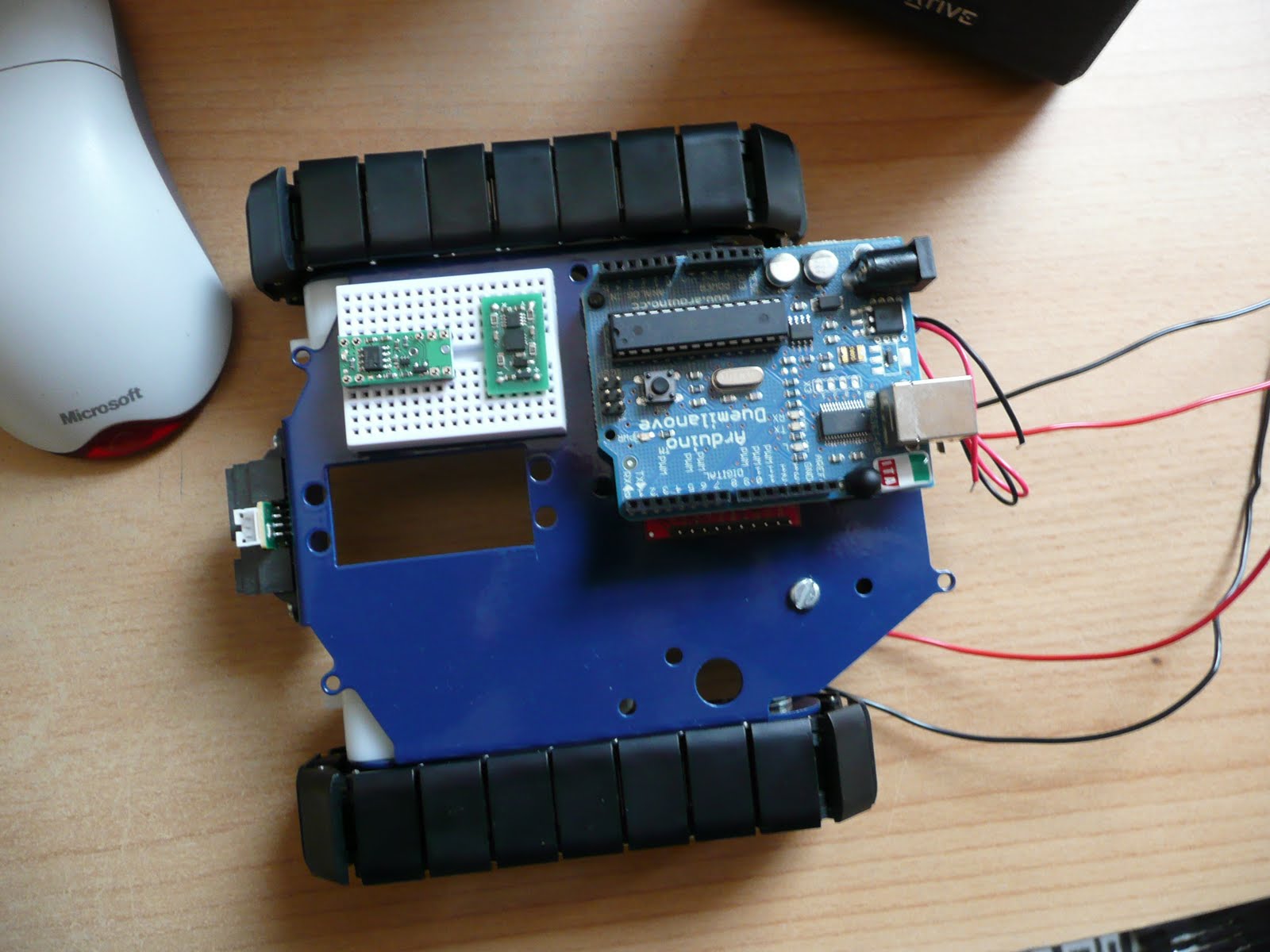
As mentioned in a previous blog entry, I have assembled the RobotShop Robot Rover for Arduino tank kit. I followed the excellent assembly video here.

On the front there is a Sharp IR sensor (GP2Y0A21YK). It's three wires (Vo, Gnd, Vcc) are fed underneath the chassis and emerge through a hole. These three wires have also had male jumper leads spliced onto them, to make it easier to test via a breadboard. The 9V battery wires, and four motor wires are also routed through the chassis.

From my first robot I have some standoffs that fit nicely to the servo mounting points on the chassis (Pololu standoffs). I also have the CMUCam3 assembled and ready for use, once the main robot is up and running. Note: that this won't be the final camera module. The CMUCam3 is just ready for me to use now. I need to get two cameras huddled on the front of Burt for stereo vision libraries.

Underneath the chassis the four 1.5V batteries and 9V battery are ideally placed to connect to the motor controller and micro controller.

On the left of the video is a hint as to the next update. The testing of the ProtoShield, IR sensor, PowerSwitch, and Accelerometer.

Sunday, 6 June 2010

[Burt] What are the chances?

I was flabber-gasted to discover that no one in the world has ever thought of creating a Google Code project called 'burt'!! I must omit that the project name came before checking with Google Code to see if it could exist as a project name :D

I've just finished the initial Google Code Project setup. The main index is here, and also in this blogs 'Handy Links' section on the right of this page.

Why 'Burt'? I may hear you cry. Simples really. "The Dukes of Hazzard" remake was on the TV at the time when I was trying to decide on the name, and Burt Reynolds steals every scene he's in.

Project: Burt

Introduction

After a couple of years of life changes, the itch to revisit robotics has taken hold. The first robot was something that I rushed into and made some crutial, and costly, design mistakes. This time around I have had time to revisit new products and come up with a new robot design, 'Project: Burt'.

It's been great re-visiting web sites and forums I have been to before, such as Sparkfun and Pololu. It was also encouraging to find two UK suppliers that I hadn't seen before, namely Cool Components and SK Pang.

Being away from the home-brew robotics community, for almost a year and a half, has meant that I had some catching up to do with the evolution of robotics parts. Immediately three parts jumped out at me; Robot Rover for Arduino (Tank Kit), Serial Controlled Motor Driver (ROB-09571, ATMega328), and the Arduino Duemilanove (ATMega328).

The ATMega328 used in the Duemilanove and Serial Controlled Motor Driver (SCMD), looks like a perfect micro-controller to use as a sensor analyser and communications hub. Plenty of digital IO and analog inputs to play with. It was a bit overwelming, and warming, to see the rise of the Arduino products. A heathy development community has sprung up. As I thought about various sensors, controllers, communication sub-systems, most of my questions as to what to use, and how to use/connect them, were answered via Arduino's wonderfull web portal and forums.

Design List

Within a few weeks my thoughts for 'Project: Burt' were starting to come together. As a starting list I had the following in mind;

Arduino Duemilanove
- As the main controller.

Robot Rover for Arduino
- As the main chassis.

Serial Controlled Motor Driver
- As the motor controller (incl. overcurrent detection).

Pololu Pushbutton Power Switch LV
- As a potential power switch for the motor controller.

Dimension Engineering Accelerometer (DE-ACCM2G)
- A buffered ±2g accelerometer based on the Analog Devices ADXL332.

IR Range Sensor (Sharp GP2Y0A21YK)
- Included with the Robot Rover kit.

Ordering

Two orders later, I have a desk full of parts :)


Included in the orders we're a handfull of other goodies; An Arduino Starter kit (C), an Arduino ProtoShield Kit, and a couple of MCP23008 and MCP23016 IO extenders (with I2C interface) for future expansion (e.g. LED segments, Servos, USB host connection, VirtualCogs interfacing, etc.).

Physical Layout


The Arduino is placed on two stand-offs, so there is about a 1cm space below it to mount the motor controller. If any heat issues arise there are other mounting holes on the chassis to use. But for the moment this looks like a good starting point.

The main boards that need individual testing;


And so, it begins

Over the next few weeks (months) I'll be continuing along like my first robot blogging. Fleshing out the Google code project with links, Arduino PDE code, Eagle schematics, more photos and videos. A detailed step-by-step guide to getting Burt up and running.

Unlike the muddled mess that was my first robot, Burt is so far shaping up to be a nice project to get back into robotics. Plus a new starting point for vision experiments. Maybe I'll be able to get the old Virtual COGs boards dusted off and make use of the lovely Freescale i.MX21 266MHz ARM9 processor, and maybe save up for something like the Surveyor Stereo Vision System...

Tuesday, 13 January 2009

Turbulent times

The end of last year became very turbulent, and resonates through the start of this year for me :( The company I have been contracting for is closing at the end of this week. And in light of the current economic climate it could be tricky to pick up new work. Mistakes made in initial purchase of parts for the robot put a spanner in the works, and it looks like it'll take some time to rectify that and purchase more appropriate parts. Need to keep a roof over my head first :) In the meantime though I do intend to get the bottom of using QTe using the only stable version of Linux I have on the COG system..