Search This Blog

Showing posts with label Pololu. Show all posts

Sunday, 6 June 2010

Project: Burt

Introduction

After a couple of years of life changes, the itch to revisit robotics has taken hold. The first robot was something that I rushed into and made some crutial, and costly, design mistakes. This time around I have had time to revisit new products and come up with a new robot design, 'Project: Burt'.

It's been great re-visiting web sites and forums I have been to before, such as Sparkfun and Pololu. It was also encouraging to find two UK suppliers that I hadn't seen before, namely Cool Components and SK Pang.

Being away from the home-brew robotics community, for almost a year and a half, has meant that I had some catching up to do with the evolution of robotics parts. Immediately three parts jumped out at me; Robot Rover for Arduino (Tank Kit), Serial Controlled Motor Driver (ROB-09571, ATMega328), and the Arduino Duemilanove (ATMega328).

The ATMega328 used in the Duemilanove and Serial Controlled Motor Driver (SCMD), looks like a perfect micro-controller to use as a sensor analyser and communications hub. Plenty of digital IO and analog inputs to play with. It was a bit overwelming, and warming, to see the rise of the Arduino products. A heathy development community has sprung up. As I thought about various sensors, controllers, communication sub-systems, most of my questions as to what to use, and how to use/connect them, were answered via Arduino's wonderfull web portal and forums.

Design List

Within a few weeks my thoughts for 'Project: Burt' were starting to come together. As a starting list I had the following in mind;

Arduino Duemilanove
- As the main controller.

Robot Rover for Arduino
- As the main chassis.

Serial Controlled Motor Driver
- As the motor controller (incl. overcurrent detection).

Pololu Pushbutton Power Switch LV
- As a potential power switch for the motor controller.

Dimension Engineering Accelerometer (DE-ACCM2G)
- A buffered ±2g accelerometer based on the Analog Devices ADXL332.

IR Range Sensor (Sharp GP2Y0A21YK)
- Included with the Robot Rover kit.

Ordering

Two orders later, I have a desk full of parts :)


Included in the orders we're a handfull of other goodies; An Arduino Starter kit (C), an Arduino ProtoShield Kit, and a couple of MCP23008 and MCP23016 IO extenders (with I2C interface) for future expansion (e.g. LED segments, Servos, USB host connection, VirtualCogs interfacing, etc.).

Physical Layout


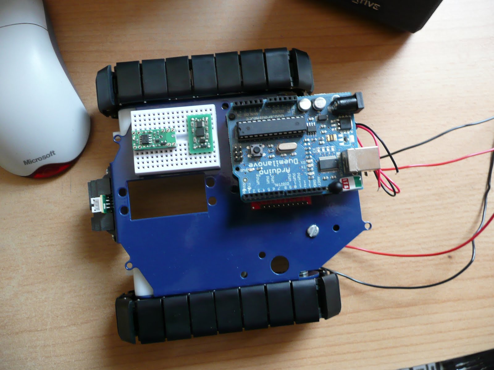
The Arduino is placed on two stand-offs, so there is about a 1cm space below it to mount the motor controller. If any heat issues arise there are other mounting holes on the chassis to use. But for the moment this looks like a good starting point.

The main boards that need individual testing;


And so, it begins

Over the next few weeks (months) I'll be continuing along like my first robot blogging. Fleshing out the Google code project with links, Arduino PDE code, Eagle schematics, more photos and videos. A detailed step-by-step guide to getting Burt up and running.

Unlike the muddled mess that was my first robot, Burt is so far shaping up to be a nice project to get back into robotics. Plus a new starting point for vision experiments. Maybe I'll be able to get the old Virtual COGs boards dusted off and make use of the lovely Freescale i.MX21 266MHz ARM9 processor, and maybe save up for something like the Surveyor Stereo Vision System...

Wednesday, 7 November 2007

CAM_RESET

I put a post on the CMUCam forum describing the problems I have with the CAM_RESET line on the CMUCam3 module. And one of the CMUCam developers kindly replied confirming my fears. That line is used to reset the OV6620 camera module, and needs to be pulled low and left along. So it can't be used as a GPIO line connected to the Pololu uDSMC reset pin :( I had thought about dropping in a transistor invertor circuit so that the CAM_RESET could be held low until a motor controller reset is required and a high pulse on that line could have reset the controller (with the appropriate HAL/OV6620 reinitialisation). But with that the mysterious half-voltage drop seen on the CAM_RESET line, it left me fearful of using that approach. Best to leave the camera alone to do it's magic.

The forum reply did make a great suggestion :) I'm only using two of the four servo outputs on the CMUCam3 (for the pan and tilt servos in the turret assembly), so have the spare two servo outputs for use as GPIO lines. I need to make some other cabling to hook it up, but great to have a proper solution for resetting the motor controller.

With that sorted I'm going to head back into the MMC code in the CMUCam3 HAL driver. Fingers crossed I can work out why the current code doesn't like the PQi MMC card I have, then onto fixing it..

Sunday, 4 November 2007

Time for some interfacing..

Before I get onto the interfacing adventure, here's an annoying problem I faced yesterday with the CMUcam3..

I picked up a cheap PQi 256MB MMC card for the CMUcam. Got back home and took the turret assembly apart to fit the MMC card. Reassembled the turret and flashed the CMUcam3 with the 'hello-world' example project. No joy trying the initial file write test in that example. Added some printfs into the HAL driver and hello-world example, and reached a 'DOH!' moment. I hadn't formatted the MMC card for FAT :(
Took turret assembly apart, formatted the MMC card for FAT, reassembled the turret, and tried again.. Still no joy :( I had a dig around further in the mmc_driver and mmc_hardware functions. Referencing datasheets on the SPI programming of an SD/MMC card, it looks like the HAL driver has very limited implementation for MMC cards. The CMUCam WIKI and forum also mention that only certain cards work and some others that CMU guys have tried don't work. So something else to add to the todo list..

Onto interfacing fun..


With the double decker chassis built earlier in the week, it was time to have a closer look at the interfacing of the three systems; VC21 stack, CMUCam3, and uDSMC. Interfacing the VC21 and CMUCam3 should be easy. The VC breakout board has UART4 to connect to the UART0 on the CMUCam3. The issue then was how to get serial data to the Pololu uDSMC board, plus the issue of how/where to get a GPIO line to the reset pin of the uDSMC.

Re-reading the CMUCam3 datasheet lead me to a mini-Eureka moment. The LPC2106 has dual UART built in and CMU have sent UART1 through to a second IDC connector on the module (the Expansion port GPIO). It also looked like the CAM RESET (P0.15) GPIO could be used for the uDSMC reset line. The UART1 sent to the expansion port is already at TTL levels, so no need for the MAX232 line driver, freeing up valuable space for the DE-ACCM2G accelerometer board :)

I made a cable to connect the expansion port IDC socket to the breadboard (only need three lines from it, GND, CAM RESET, and TX2). Then onto changing the 'CMUCam2 emulator' example project to handle GPIO changes and UART1.


It took a little bit of work to get the CAM RESET GPIO setup. The below code is now used to initially select P0.15 as a GPIO output, pull it low for 100ms, before turning it high and keeping it high.
// CAM RESET(P0.15) bit selector
#define CAM_RESET 0x00008000
// Make P0.15 a GPIO
REG(PCB_PINSEL0) = REG(PCB_PINSEL0)&0xCFFFFFFF;
// Set P0.15 as output
REG(GPIO_IODIR) = REG(GPIO_IODIR) | CAM_RESET;
// P0.15 low, to reset motor controller
REG(GPIO_IOCLR) = CAM_RESET;
cc3_timer_wait_ms (100);
// Raise P0.15 high
REG(GPIO_IOSET) = CAM_RESET;

The UART1 setup was a lot easier. The cc3 HAL library is already setup to handle the second UART. It was then just a simple case of adding another input command to the example code. The following shows a simple way to send serial commands to the Pololu uDSMC.

cc3_uart_init (1, CC3_UART_RATE_9600, CC3_UART_MODE_8N1, CC3_UART_BINMODE_BINARY);
FILE * fp = cc3_uart_fopen(1,"r+");
if (fp == NULL)
{
printf("UART1 is dead\n");
while(1);
}
unsigned char buf[8];
// Both motors forward at half speed
buf[0] = 0x80; // Start byte
buf[1] = 0x00; // Device type
buf[2] = (0x00<<1) | 0x1; //M1 forward
buf[3] = 0x40;
buf[4] = 0x80; // Start byte
buf[5] = 0x00; // Device type
buf[6] = (0x01<<1) | 0x1; //M2 forward
buf[7] = 0x40;
for(int i = 0; i < 8; i++)
{
while((REG(UART1_LSR) & LSR_THR_EMPTY) == 0);
REG(UART1_THR) = buf[i];
}
fflush(fp);
I don't think the fflush is needed (and might not even be setup properly) because the cc3_uart_init already setups UART1 to flush it's FIFO after 8 bytes have been written to it. I need to have a further look to see if this is the write way to write out serial data via the UART registers, and whether the HAL code is behaving and thourough.

So two extra commands have been added to that CMUCam2 example firmware image. I've hooked up the 'FW' command to send the motor on commands to the uDSMC, and added the 'MR' command to CLR and SET the P0.15 GPIO line to reset the motor controller. These commands can be sent via the CMUCam3 Frame Grabber program.


Issues..
So far this 'almost' works. The uDSMC picks up the serial commands and starts turning the motors/wheels. BUT, and a big one, is that after X milliseconds (over 400ish) the P0.15 GPIO line drops half it's voltage and I guess resets/disables the uDSMC stopping the motors. Hmmmm...

Something to look at in the week.

That's all for now folks..

Saturday, 20 October 2007

MAX232, uDSMC, CMUCam3

It's been a busy week in and out of work, so only been able to chip away at stuff.

I managed to get Irrlicht compiled and linked into a VC21 example (touch example). Plus using the Insight/GDB/OpenOCD/JTAG combo to download it to the MX21 board. It took some makefile monkey'ng to get it built though. Rolling in at a wooping 18MB elf it took quite a while to download. I only enabled a stub device and display drive, but managed to step through to the Irrlicht startup code. Although Irrlicht is quite bloated with some lovely features I intend to use in the future, it's a bit too much for this initial setup work. So for the time being that side of this project is on hold.

The Pololu chassis and motor controller testing I blogged about earlier. The initial setup of the uDSMC used the simple RS232 converter circuit described in the uDSMC manual to check all was working fine. In the week I popped into a local electrical shop and picked up a MAX232 IC and 7805 DC/DC regulator. These are now used as the main RS232 converter for the Pololu uDSMC and chassis.

A variety of schematics were used as reference to setup this circuitry, for example;
http://www.digitalnemesis.com/info/projects/picservo/article.aspx
http://www.flickr.com/photos/todbot/94701997/in/set-72057594051313379/
http://www.iguanalabs.com/adc2051.htm

The motors are powered straight from the battery source, and the MAX232 and uDSMC are powered from the 7805 regulator. This all works very nicely, and seems more stable. So far no heat problems.

It's now possible to revist the power input for this chassis. I ran out of breadboard space to add a power LED and power switch, so need to look into that at a later date. I'm also only using half of one of the dual RS232 line drivers inside the MAX232 (to pull down the RS232 signals to TTL levels needed for the uDSMC), but it does allow for future expansion. It's now possible to add quite a variety of other TTL based devices to this circuit (e.g. sensors, alternative motor drivers). Eventually I'll transfer this to a stripboard and clean up the cabling and power connections.

Once complete I revisited the custom communication software I wrote to talk to the uDSMC. Adding to it a different way of handling cursor keys from the laptop, and using linear ramping for the speed sent to the uDSMC. Still need to revist the braking side of that code, but it was happily moving around the desk controlled from the laptop.


While setting up different software test harnesses, I had intended to start using Eclipse as my main IDE. Annoyingly though Eclipse does some daft things. It's quite an alien IDE to me, so I've ended up ditching it in favour of Visual Studios Express Edition (again free). Creating an extensive makefile system, with proper dependency checking etc. I can now use this as a template build system for further SW development. Insight and OpenOCD are also included in this setup.

Inow have a Subversion server running on the laptop. After many years using RCS it is now ingrained in my SW development pipelines. We currently use SVN at the company I'm working for. It's fairly nice, has it's quirks of course, but it's a lot better than VSS. Thinking about it though I could have grabbed Perforce to handle the SCM/RCS, but then SVN and it's shell integration works well enough.
This setup actually turned out to be really simple. Head on over to http://svn1clicksetup.tigris.org/ for a single installer based method for setting up SVN and your first repository :)


At the end of week the CMUCam3 module arrived from Seattle Robotics :)

Need to pop to the shops today to pickup a power connector for this, then I can check it out and have a play. Can't wait... :)

Sunday, 14 October 2007

Pololu chassis up and running...


Yesterday I had great fun setting up the Pololu chassis and controlling it via serial communication from the laptop :) After trying out my soldering on a test kit from Maplin (two LED flashing unit), I started work on the chassis and breadboard work for this ickle robot.

As recommended I soldered a 0.1uF Cermamic capacitors across the two motors and feed each pair of wires from the motors through the chassis to the breadboard. The USB-RS232 connector fed the four serial lines required through to the breadboard, with a simple transistor (2N2222A, high frequency, low power) and resistor arrangement to bring the RS232 levels down to the levels required by the Pololu micro dual serial motor controller. This could then be sent a serial bit stream that the controller would interpret and drive the internal H-Bridge to control the two chassis motors.

I had some teething trouble at first by making the mistake of driving the motor controller logic levels at too high a voltage. Ending up with a smoking motor controller :S Thankfully I had bought two of them just in case this happened.

To send the control data to the motor controller ended up being very simple. A Win32 console app, built through the free Visual Studio 2005 Express Edition IDE, opened up and setup the appropriate COM port that the USB-RS232 converter had mapped itself too (under WinXP). Configured to 9600bps, no parity, 1 stop bit, DTR/RTS turned off, and FILE_FLAG_WRITE_THROUGH|FILE_FLAG_NO_BUFFERING used in the CreateFile call to make sure device writes were not cached (although I also used FlushFileBuffers after each WriteFile just in case). It was then a simple matter of using WriteFile to send the 4 bytes worth of data to the motor controller to control the motor states. Some additional GetAsyncKeyState monkeyness allowed for forward/back/left/right movement control.

Apart from frying the original controller, and making sure that stalls didn't kick in the motor controller thermal cutoff protection, everything went very smoothly. Although this is just novice entry level experiments to get a chassis built and moving, it's a nice starting point. I can now do some stress testing of the chassis and controller, see how they fair with carrying heavier loads, and work out what improvements/replacements need to be made for the final chassis and motor control. But before that, I'm going to switch back to the JTAG debugging investigation/learning with the COGs, and setting up a decent makefile workspace (either in Eclipse or VS EE, not sure yet).

Friday, 28 September 2007

CMUcam turret assembly

I've had the CMUcam turret assembly sitting in a box for the last week (ordered from http://www.robot-electronics.co.uk/) waiting for certain missing tools to turn up. They turned up on Wednesday, but a party last night delayed the initial assembly. I'm also waiting on the CMUcam3 module turning up from Seattle. In the mean time I thought I'd get it built and see what size it built to. The size certainly shows that the Pololu chassis is going to be too small.

Monday, 24 September 2007

First arrival

The first parts have turned up :)

Pololu have delivered the two Round Robot Chassis. And now I see how tiny they are :S Only took an hour of fun to assemble one of them. I'll keep the other for a spare, or for other robot/sensor experiments.


Sunday, 23 September 2007

Shopping list (part 1)

I recently came across a, relatively, new Canadian company called Virtual Cogs (http://www.virtualcogs.com/). Their VC21 series of stackable devices is superb. I'd used ARM processors before in handheld game programming, and always like their chips. So seeing them used on a VC21 stack modules got me thinking about making a robot again.

VC's Robot COG looked perfect as the main HW interface, with the i.MX212 handling the bulk of any SW processing. Throw in the Multimedia COG with touch screen, Linux running on the i.MX212, integrated JTAG, and lots of new avenues open.

So first on the shopping list is;
  • i.MX212 COG (VCMX212) (Actually went for the Starter Kit)
  • Breakout COG (VC21BR1)
  • Multimedia COG (VC21MM1)
  • Robot COG (VC21RB1)
  • JTAG interface (VC21JTAG)
  • Assorted connector cables and mounting hardware
The next step was Pololu's robot kits (http://www.pololu.com/). Particularly the Round Robot Chassis. Impetuously I went ahead and ordered the chassis kit, with Tamiya gearbox and assorted plates. Only later reading up on the H-Bridge used in the VC21RB1 :S More on that later.
Plus it was also later that I discovered that I could have bought them from Technobots Ltd here in the UK (http://www.technobots.co.uk/). Oh well, another supplier found...

Next up was the JTAG interface. For which I went for the Olimex (http://www.olimex.com/dev/index.html) ARM-USB-TINY and ARM-JTAG (as backup, just in case OpenOCD had trouble with the USB varient). Ordered these via Sparkfun Electronics (http://www.sparkfun.com/).

Another great find is the CMUCAM2 and, importantly, the pan/tilt turret head and servos. This time I got it from Active-Robot :) (http://www.active-robots.com/products/accessories/cmucam.shtml). Only one of these to start with, but I'll grab another further down the line.

Finally, in this first line of purchases, is a cheap laptop from eBay. Took a couple of days to win a good bid, but managed to get an IBM Thinkpad T42 for under £200.

Yay, first purchasing round is complete. Now just need to wait for it all to turn up.

In the mean time I can start at getting together all the development software required...